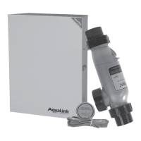
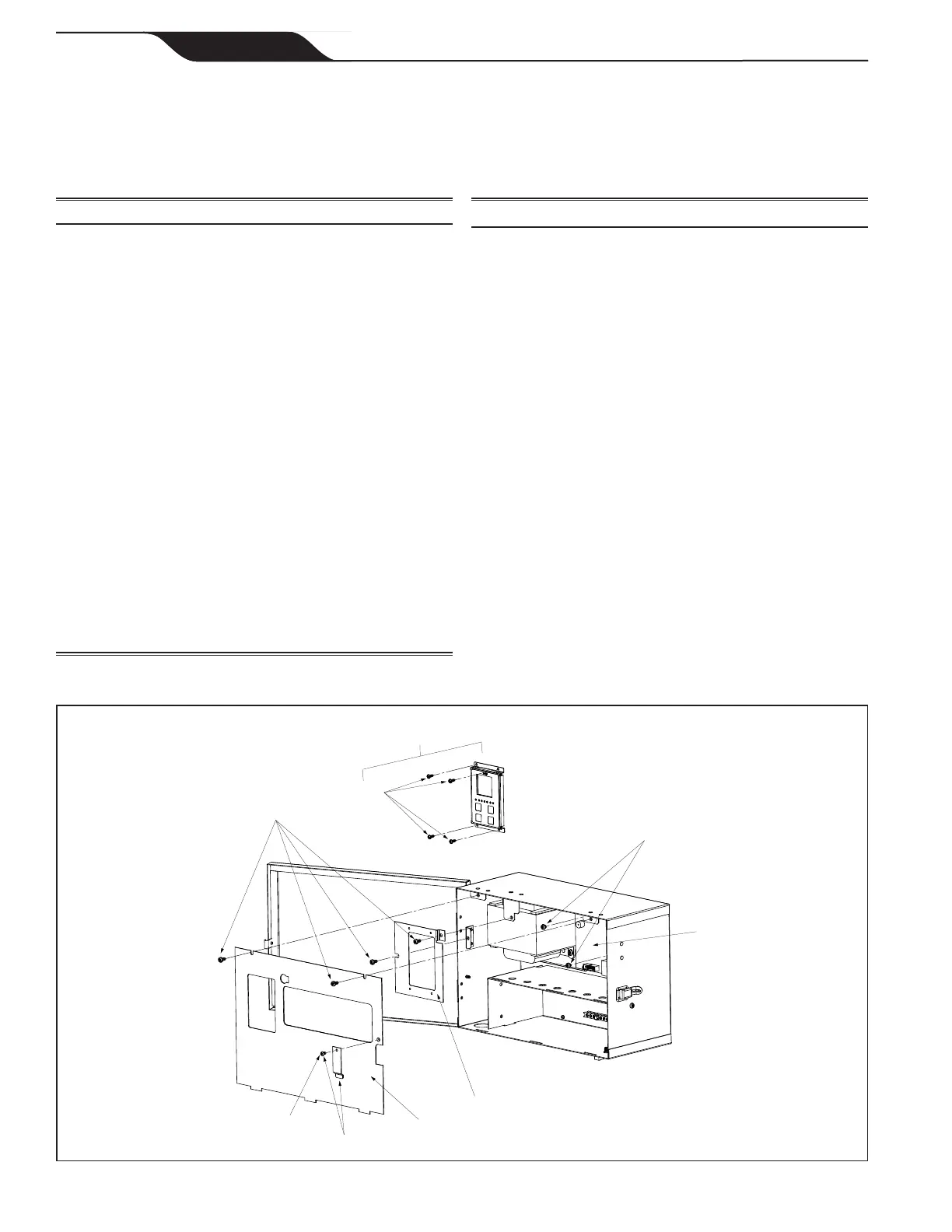
Figure 20a. AquaPure Control Center
Dwg.# Kit # Description Qty.
1 R0467400 User Interface Board
Screws
1
4
2 R0467700 Bezel Cover Plate, PureLink
Power Center
Bezel Support Plate, PureLink
Power Center
Battery Cover, PureLink
Power Center
Screws, Bezel Cover Plate
Screws, Bezel Support Plate
Screw, Battery Cover
1
1
1
2
2
1
3 R0447300 Battery Door, PureLink Power
Center
Screw, Battery Cover
1
1
4 R0467800 Screws, User Interface, PureLink
Screws, Power Interface Assy
Screws, Bezel Cover Plate
Screws, Bezel Support Plate
Screw, Battery Cover
4
2
2
2
1
Dwg.# Kit # Description Qty.
5 R0447500 Wiring Harness, PureLink Back
PCB to DC Cord
1
6 R0467600 Power Interface Board Assembly
Screws, Power Interface
1
2
7 R0503400 Face Plate, Control Center,
APURE-F
Mounting Bracket, User Interface,
APURE-F
Screws, User Interface Mounting
Bracket and Face Plate
Battery Door, Control Center,
APURE-F
Screw, Battery Cove
1
1
4
1
1
8 R0503300 Battery Door, Control Center,
APURE-F
Screw, Battery Cover
1
1
Section 9. AquaPure and PureLink Exploded Views and
Replacement Kits
9.1 AquaPure and PureLink Control/Power Center Replacement Parts
1
4
4
4, 7
6
7
7
4, 6
7, 8
Page 46
ENGLISH
Page 46
ENGLISH
Jandy
®
AquaPure
®
/PureLink™ Power Center and Cell Kit
|
Installation and Operation Manual