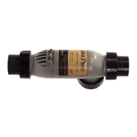
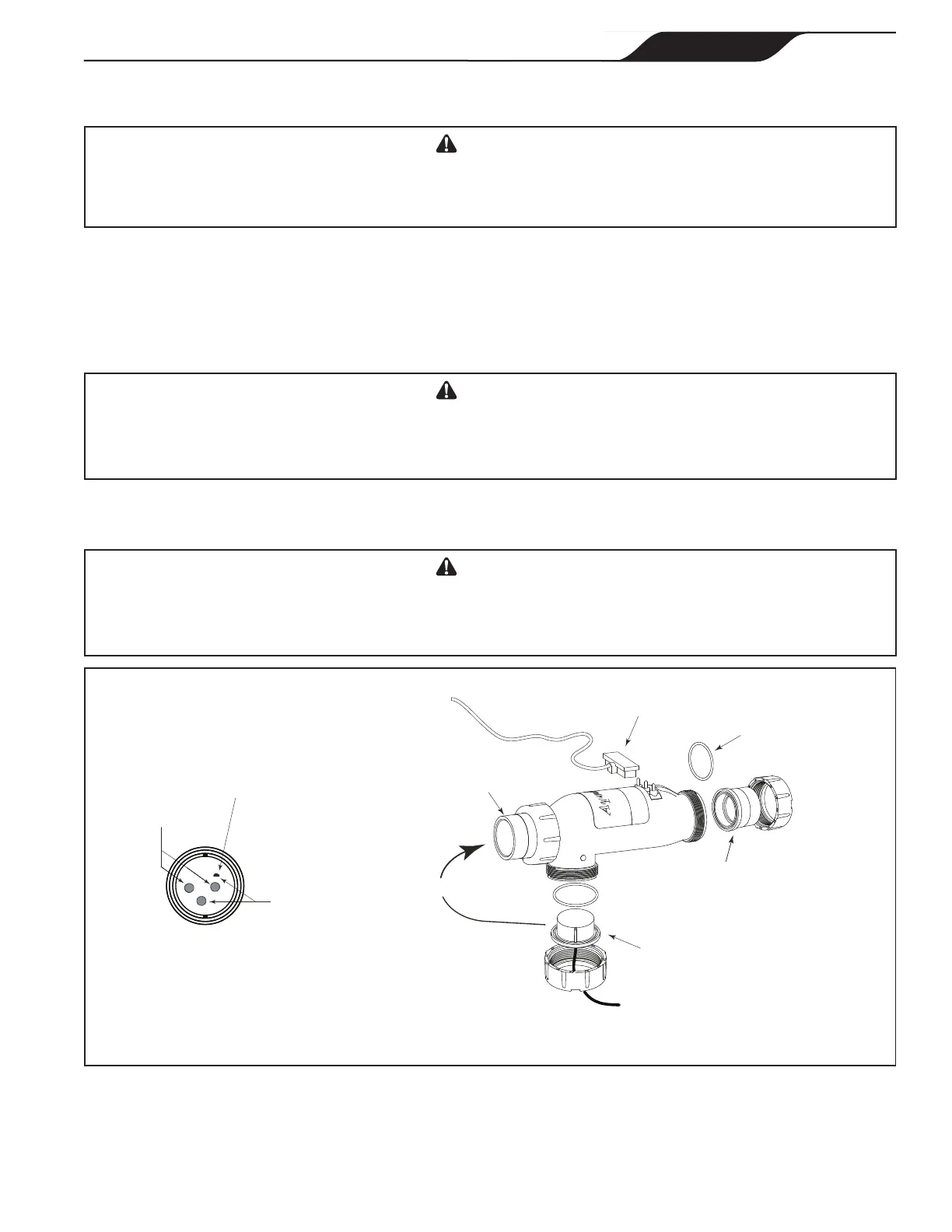
Figure 11. Cell Installation and Flow/Temp/Salinity Sensor
* Ensure the DC Plug is properly and securely
connected to the terminal studs of the cell.
DC Cord Plug is Connected
to Terminal Studs*
O-Ring
Seal
Flow/Temp/Salinity Sensor
O-ring and Union Nut
2 x 2½” or 50mm Tailpiece
with Coupling Nut
2” x 2½” or
50mm Union
or
Sometimes
Not Covered
Temperature
Sensors
Flow/Temp/Salinity Sensor Face must
be clean at all times for proper operation
Salinity
Studs
5. Connect the DC cord to the control center. Feed the DC cord through the same strain relief tting as the
ow/temp/salinity sensor. Plug the DC cord as shown in Figure 2a, 2b, and 2c.
CAUTION
Do not bury the electrolytic cell DC cord or Sensor cable directly in the ground. Direct burial can cause
damage to an electrical cord/cable.
6. Tighten strain relief tting screws for the ow/temp/salinity sensor cable and the DC cord. Do not pull
ow/temp/salinity sensor cable or DC Cord too tight. Allow a little cable slack inside of control center
enclosure.
7. Check the wiring prior to reattaching front cover. Be sure the ow/temp/salinity sensor is plugged in.
The DC cord should be plugged in. Also, check the AC wiring.
CAUTION
Donotovertightenthestrainrelieftting.Overtighteningcancausedamagetotheow/temp/salinity
sensor cable.
8. If disconnected, plug the ribbon cable into the J1 connectors the user interface and the Power Interface
PCB (See Figures 2a, 2b, 2c, and 10).
CAUTION
Donotoperatetheelectrolyticcellwithoutwatercirculation.Abuildupofammablegasescanresultin
FIRE or EXPLOSION.
Page 21
ENGLISH
Page 21
ENGLISH
Jandy
®
AquaPure
®
/PureLink™ Power Center and Cell Kit
|
Installation and Operation Manual