3a. Option 1 - Retain Existing Sensor in Threaded Tee
a. Remove old 2-Port cell body by unscrewing coupling nuts on ports. The cell body will be free to a. Remove old 2-Port cell body by unscrewing coupling nuts on ports. The cell body will be free to
pull out after nuts are clear of the threads.pull out after nuts are clear of the threads.
b. Replace existing union o-rings with new o-rings provided with cell kit.b. Replace existing union o-rings with new o-rings provided with cell kit.
c. Install new cell and tighten coupling nuts. c. Install new cell and tighten coupling nuts.
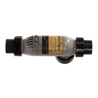
NOTE 3-PortCelland2-Portcellarethesamelength.Thenewcellshouldtwithoutanyneedtomodifyexisting
plumbing.
d. Ensure that the 3rd port is sealed off with provided o-ring, plug and nut. Verify coupling nut is d. Ensure that the 3rd port is sealed off with provided o-ring, plug and nut. Verify coupling nut is
properly hand tightened.properly hand tightened.
e. Go to Step 4, below.e. Go to Step 4, below.
3b. Option 2 - Install New Sensor in 3rd Port of Cell (remove old sensor and plug tee)
a. Remove old flow/temp/salinity sensor by unscrewing it from the threaded tee.a. Remove old flow/temp/salinity sensor by unscrewing it from the threaded tee.
b. Replace sensor with 1 ½” threaded plug.b. Replace sensor with 1 ½” threaded plug.
c. Disconnect the flow/temp/salinity sensor from the Power Interface PCB as shown in c. Disconnect the flow/temp/salinity sensor from the Power Interface PCB as shown in Figure 2a, 2b,
and 2c. Loosen the strain relief fitting that also contains the cable for the DC cord. Pull the flow/. Loosen the strain relief fitting that also contains the cable for the DC cord. Pull the flow/
temp/salinity sensor cable out through the strain relief. temp/salinity sensor cable out through the strain relief.
d. Remove old 2-port cell body by unscrewing coupling nuts on ports. The cell body will be free to d. Remove old 2-port cell body by unscrewing coupling nuts on ports. The cell body will be free to
pull out after nuts are clear of the threads.pull out after nuts are clear of the threads.
e. Replace existing union o-rings with new o-rings provided with cell kit.e. Replace existing union o-rings with new o-rings provided with cell kit.
f. Install new cell and tighten coupling nuts.f. Install new cell and tighten coupling nuts.
NOTE 3-PortCelland2-Portcellarethesamelength.Thenewcellshouldtwithoutanyneedtomodifyexisting
plumbing.
g. Install the new flow/temp/salinity sensor into the 3-port cell (See Figure 11). g. Install the new flow/temp/salinity sensor into the 3-port cell (See Figure 11).
h. Feed the connector end of the flow/temp/salinity sensor cable through the DC cord strain relief h. Feed the connector end of the flow/temp/salinity sensor cable through the DC cord strain relief
fitting. Be certain the connector is clean and dry, then plug the cable into the connector on the fitting. Be certain the connector is clean and dry, then plug the cable into the connector on the
Power Interface PCB as shown in Power Interface PCB as shown in Figure 2a, 2b, and 2c (Do not pull flow/temp/salinity sensor (Do not pull flow/temp/salinity sensor
cable too tight, allow a little slack).cable too tight, allow a little slack).
i. Go to Step 4, below.i. Go to Step 4, below.
3c. Option 3 - Replace Section of Piping (eliminate old cell and sensor ttings) and treat as New
Installation.
a. Cut out section of pipe that contains cell, sensor, and fittings. Glue straight couplers or reducing a. Cut out section of pipe that contains cell, sensor, and fittings. Glue straight couplers or reducing
coupler onto open ends of piping. Make sure to leave enough length to fit in new cell (see Figure coupler onto open ends of piping. Make sure to leave enough length to fit in new cell (see Figure
13).13).
b. Go to Step 1, Section 3.7.1.New Installationb. Go to Step 1, Section 3.7.1.New Installation
4. Plug the DC cord, in either direction, into the cell stud terminals protruding from the cell top. Make
sure that the plug is fully inserted and bottomed out on the housing.
CAUTION
Toavoidriskofdamagetotheequipmentandpossibleinjury,itisimportanttomakesuretheDCcable
connector is fully seated on the cell stud terminals.
Page 20
ENGLISH
Page 20
ENGLISH
Jandy
®
AquaPure
®
/PureLink™ Power Center and Cell Kit
|
Installation and Operation Manual
 Loading...
