Page: 121
MV & LV SERIES ENGINEERED DRY CHEMICAL FIRE EXTINGUISHING SYSTEM
OPERATION, DESIGN, & SERVICE MANUAL
REV C
Document # DOC324
Issued: April 26, 2018
Revised: March 22, 2022
UL FILE # EX27541
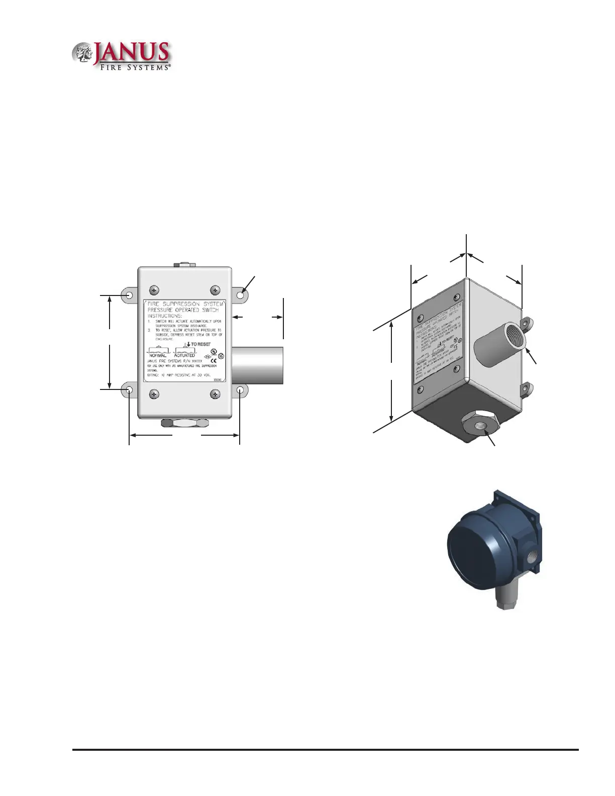
Figure C.1.2 Discharge Pressure Switch
3.375 in
85.7 mm
2.875 in
73.0 mm
3/16”
(4.76 mm)
Mounting Hole
1.56 in
39.6 mm
C.1.2 Discharge Pressure Switch
P/N 18773 (See Figure C.1.2)
A discharge pressure switch is used in the system to send a signal confirming agent discharge to the control
panel or to initiate the shut down of equipment that may deplete agent concentration. It is a single pole,
double throw (SPDT) switch with contacts rated 10 Amps resistive at 30 VDC. e discharge pressure
switch shall be required where mechanical system actuation is possible, though its placement varies according
to the individual system arrangement.
REPLACEMENT COMPONENT: Refer to Section 2.4.2 of this manual for the equivalent replacement
component.
Figure C.1.3 Explosion-Proof
Pressure Switch
C.1.3 Explosion-Proof Discharge Pressure Switch
P/N 16384 (See Figure C.1.3)
e J120-192 Explosion-Proof Discharge Pressure Switch is used in
potentially explosive atmospheres to send indication of agent discharge
to a releasing panel and/or initiate the shut down of equipment that may
deplete agent concentration. It is a single pole, double throw (SPDT)
switch with contacts rated 15 Amps at 125/250/480 VAC resistive.
e J120-192 must be manually reset by turning the Manual Reset
knob in the direction indicated on the knob itself.
REPLACEMENT COMPONENT: Refer to Section 2.4.2 of this manual for the equivalent replacement
component.
1/2” (15 mm)
Conduit Entry
1/4” (8 mm)
FNPT Pipe
Connection
2.88 in
73.2 mm
4.63 in
117.6 mm
2.90 in
73.7 mm
Appendix C
 Loading...