Page: 64
MV & LV SERIES ENGINEERED DRY CHEMICAL FIRE EXTINGUISHING SYSTEM
OPERATION, DESIGN, & SERVICE MANUAL
REV C
Document # DOC324
Issued: April 26, 2018
Revised: March 22, 2022
UL FILE # EX27541
3.5 Pipe Determination
Pipe sizes must be determined using the Janus
Design Suite® flow calculation software.
Table 3.5 may be referenced for the purposes
of estimation. e actual diameters may vary
due to distance or software optimization.
Flowcalculationshavebeenveriedatanambienttemperatureof70°F(21.1°C).Storageoutsideoftherange
of70°F±10°(21.1°C±5.5°)mayresultininaccurateowcalculationsandcauseoneormorenozzlestonot
discharge the designed quantity of dry chemical agent.
Flowcalculationshavebeenveriedforspecictypesofttings,pipeandpipeID.Failuretomaintaintheveried
limitationsasstatedintheJanusDesignSuite®FlowCalculationSoftwareManualmayresultininaccurateow
calculations and cause one or more nozzles to not discharge the designed quantity of dry chemical agent.
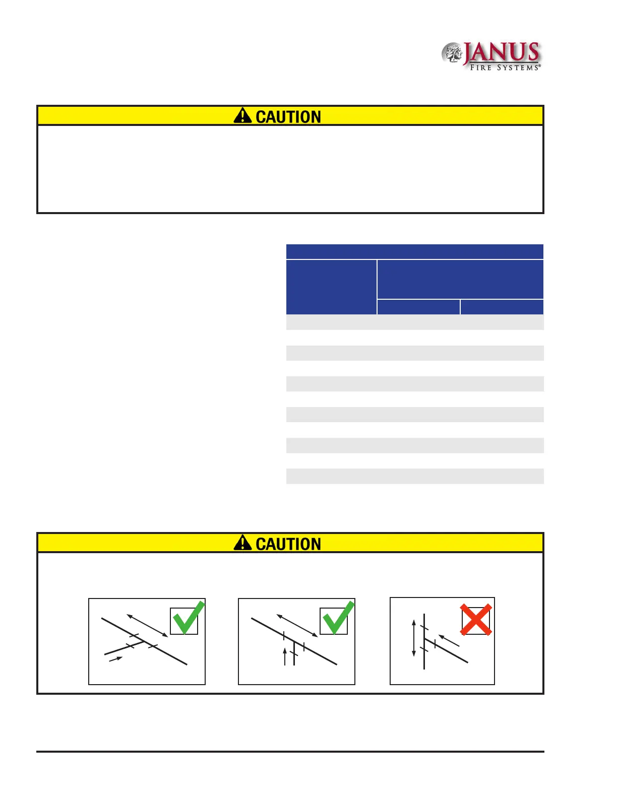
The outlets of a tee branch must be on the same horizontal plane or an imbalance will result from the gravitational
eectsofthesolidandvaporseparationandmaycauseoneormorenozzlestonotdischargethedesigned
concentration of dry chemical agent.
IN
OUT
OUT
OUT
IN
IN
OUT
OUT
Table 3.5 - Pipe Size vs. Flow Rate
Schedule 40
Pipe Size Nomi-
nal Inches (mm)
Minimum Flow
Rate For All
Sections Leading to a Tee
Lbs/Min Kg/Min
3/8 (10) 46.5 21.1
1/2 (15) 77.4 35.1
3/4 (20) 136.2 61.8
1 (25) 219 99.3
1 1/4 (32) 380.4 172.5
1 1/2 (40) 523.8 237.6
2 (50) 894.6 405.8
2 1/2 (65) 1321.8 599.5
3 (80) 2140.2 970.8
4 (100) 3878.4 1759.2
6 (150) 8596.2 3899.2
Section 3 System Design
 Loading...