Page: 16
MV & LV SERIES ENGINEERED DRY CHEMICAL FIRE EXTINGUISHING SYSTEM
OPERATION, DESIGN, & SERVICE MANUAL
REV C
Document # DOC324
Issued: April 26, 2018
Revised: March 22, 2022
UL FILE # EX27541
Section 2 System Components and Description
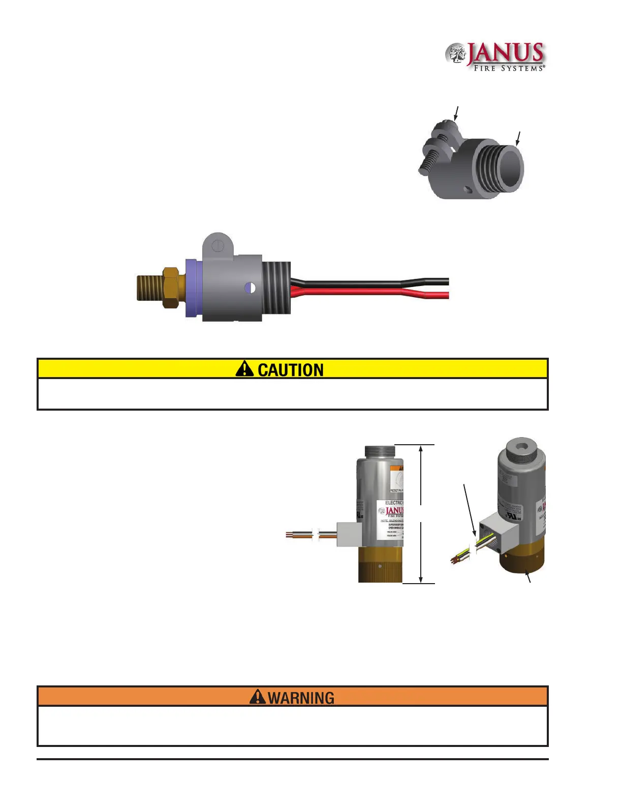
Figure 2.2.3a Electric Valve Actuator
Knurled Swivel Nut
1/2” (15 mm) NPS Female
Conduit Hub
with 40” (1016 mm) leads
1/2" (15 mm) NPS
Male Conduit
Connection
Figure 2.2.2.1a Low-Pressure
Supervisory Switch Conduit Adapter
Figure 2.2.2.1b Low-Pressure Supervisory Switch w/ Conduit Adapter (Sv Series Shown)
Attaching the electric valve actuator to the cylinder valve or remote actuation cylinder when the actuation pin is
not fully locked into the “up” position may cause the cylinder valve to actuate, resulting in potential injury and/or
property damage.
The conduit adapter fastening screw shall NOT be overtightened. Overtightening the fastening screw may cause
the body of the low-pressure supervisory switch to crack.
NOTE: Conduit Adapter must be ordered sepa-
rately from the low-pressure supervisory switch
andeldinstalledasshownhere.
2.2.2.1 Low-Pressure Supervisory Switch Conduit Adapter
P/N 99408 (See Figure 2.2.2.1a and 2.2.2.1b)
An optional conduit adapter is available for the low-pressure supervisory
switch to facilitate the attachment of rigid or flexible conduit over the
switch leads. When implemented, the adapter shall be field installed to
the body of the low-pressure supervisory switch and the fastening screw
secured until the conduit adapter fits snuggly around the low-pressure
supervisory switch body as illustrated in Figure 2.2.2.1b.
2.2.3 Electric Valve Actuator w Limit Switch
P/N 20722 (See Figure 2.2.3a)
e electric valve actuator attaches to the
primary cylinder at the valve actuation
connection in a single cylinder system or the
remote nitrogen actuation cylinder in multiple
cylinder system. It is utilized to automatically
open the cylinder valve upon receipt of a
signal from the control panel or other source.
It operates between 20.4 and 26.4 VDC and
consumes 500 mA (.5 Amps) at 24 VDC
nominal with a maximum supervisory current
of 30 mA (0.03 Amps).
e electric valve actuator body is steel construction with a brass knurled swivel nut and a stainless steel actuation
pin that depresses the valve core when energized. It must be manually reset by pushing the pin up until it snaps in
the “up” position. e electric valve actuator is shipped with a plastic threaded cap on its top port that should only
be removed when installing the manual valve actuator. e electric valve actuator has a life span of 25 years from
date of manufacture.
5.11 in
129.8 mm
Fastening Screw
 Loading...