Page: 17
MV & LV SERIES ENGINEERED DRY CHEMICAL FIRE EXTINGUISHING SYSTEM
OPERATION, DESIGN, & SERVICE MANUAL
REV C
Document # DOC324
Issued: April 26, 2018
Revised: March 22, 2022
UL FILE # EX27541
Section 2 System Components and Description
2.00 in
50.8 mm
1.620 in
41.15 mm
Ring Pin
Emergency
Release Button
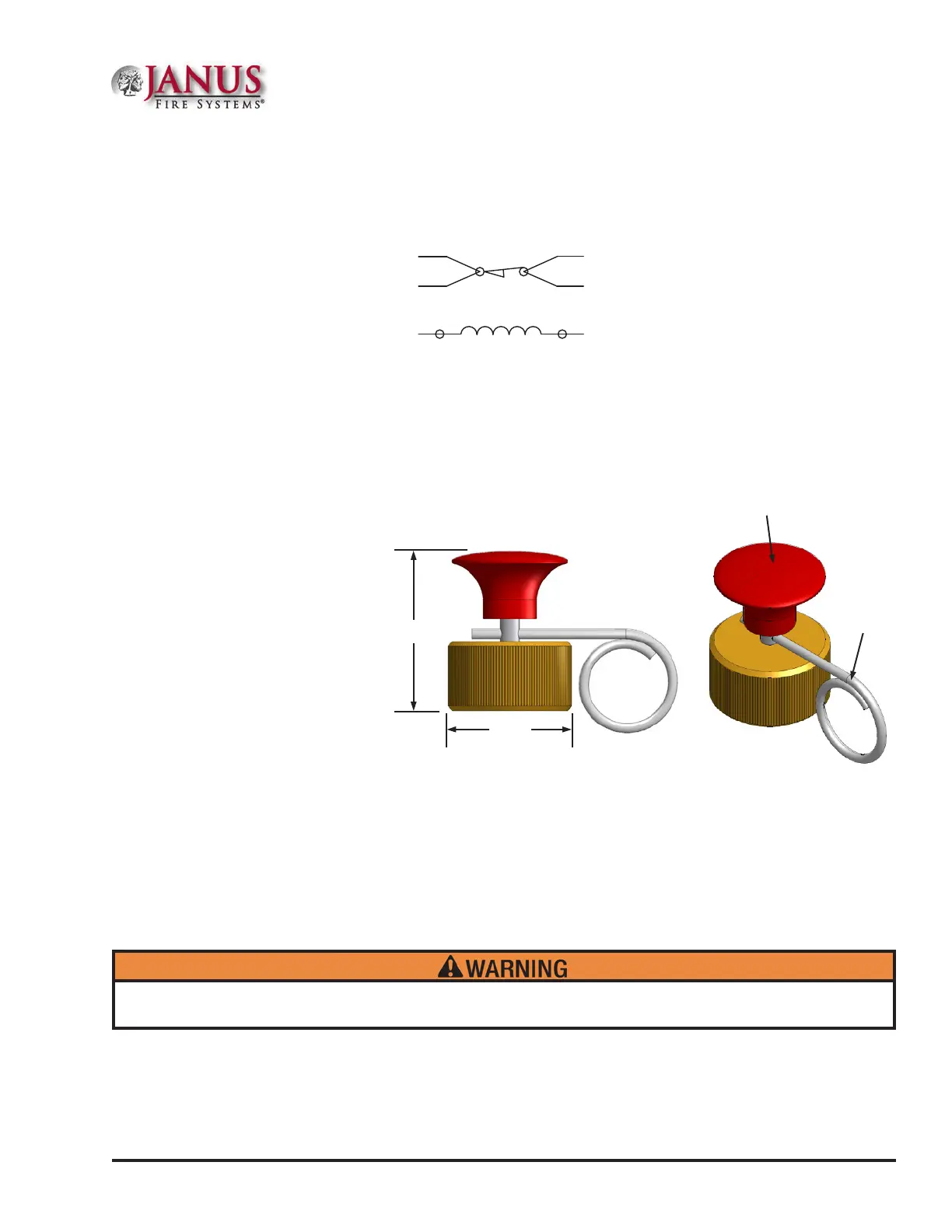
Figure 2.2.4 Manual Valve Actuator
SOLENOID COIL
ORANGE WIRE
ORANGE WIRE
YELLOW WIRE
YELLOW WIRE
WHITE WIREBLACK WIRE
Figure 2.2.3b Electrical Valve Actuator w/ Limit Switch Wiring Diagram
e electric valve actuator has limit switch contacts that are normally closed when the actuator is not installed
onto the cylinder valve/remote pneumatic actuator. When the actuator is fully installed onto the valve actuation
connection at the top of the cylinder valve, the limit switch contacts open. (See Appendix C for additional options).
2.2.4 Manual Valve Actuator
P/N 17001 (See Figure 2.2.4)
A manual valve actuator is
attached to the top of the
electric valve actuator to provide
a means for emergency manual
operation of the cylinder valve
in a single system or the remote
nitrogen actuation cylinder
in a multiple cylinder system.
(Note: e manual valve
actuator cannot be attached
directly to the cylinder valve. )
NOTE: Electric Valve Actuators with a 1/2 in (15 mm) Conduit Hub (P/N 20722) must be installed with flexible
metal or liquid tight conduit in compliance with all local, state, national and/or international building codes. Refer
to DOC323 Electric Actuator Installation Sheet for a list of UL Listed connectors that meet the requirements of
Underwriters Laboratories and are suitable for use with these actuators.
e manual valve actuator consists of a brass body, stainless steel actuation pin, and steel safety ring pin.
To discharge the secondary cylinder(s) manually, the ring pin is removed and the emergency release button
is depressed forcing the actuation pin in the electric valve actuator to depress the valve core of the nitrogen
actuation cylinder valve. All other connected cylinders will then open pneumatically. e manual valve actuator
is reset by pulling up on the palm button and inserting the ring pin.
Attaching the manual valve actuator to the electric valve actuator when the actuation pin is not fully locked into
the “up” position may cause the cylinder valve to actuate, resulting in potential injury and/or property damage.
 Loading...