Page: 20
MV & LV SERIES ENGINEERED DRY CHEMICAL FIRE EXTINGUISHING SYSTEM
OPERATION, DESIGN, & SERVICE MANUAL
REV C
Document # DOC324
Issued: April 26, 2018
Revised: March 22, 2022
UL FILE # EX27541
Section 2 System Components and Description
2.3.3 Pneumatic Valve Actuator
P/N 17019 (See Figure 2.3.3)
In multiple cylinder systems, a pneumatic valve
actuator is attached to each cylinder at the valve
actuation connection. It receives pressure from
the remote nitrogen actuation cylinder through
the pilot actuation line. When the electric valve
actuator opens the remote nitrogen actuation
cylinder, pressure from the remote cylinder
causes each pneumatic valve actuator to open its
attached cylinder pneumatically.
e pneumatic valve actuator is brass with a brass piston and pin. To reset the pneumatic valve actuator,
pressure must first be bled down from the pilot actuation line, the pneumatic valve actuator removed from
each valve, and then the actuation pin must be pushed up until the pin snaps into the “up” position.
2.3.4 Vent Check
P/N 10173 (See Figure 2.3.4)
e vent check is a safety device with 1/4 in (8 mm) male
NPT threads that is to be installed in the pilot actuation
line downstream of the pilot actuation check valve. It is
used to bleed off pressure that may accumulate in the
multi-cylinder actuation piping, reducing the chance of
inadvertent operation of pneumatic valve actuators. A
rapid accumulation of actuation pressure will cause the
nylon ball located inside the vent check to seat and seal
allowing the pneumatic valve actuators to operate as intended. After actuation, pressure must be bled down
from the pilot actuation line in order to unseat this nylon ball. is can be done by loosening a fitting along
the pilot actuation line.
Attaching the pneumatic valve actuator to the cylinder valve when the actuation pin is not fully locked into the
“up” position may cause the cylinder valve to actuate, resulting in potential injury and/or property damage.
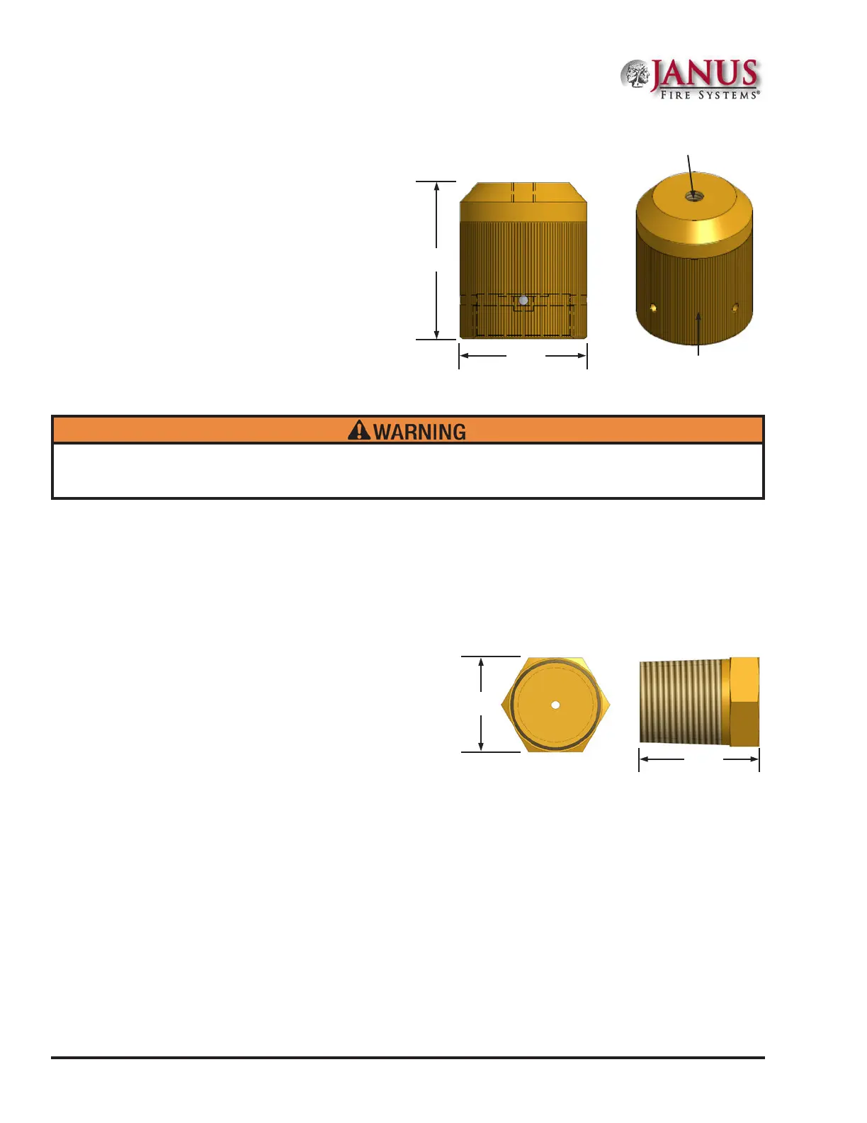
Figure 2.3.3 Pneumatic Valve Actuator
1.620 in
41.15 mm
2.00 in
50.8 mm
1/4” NPT
Inlet Port
(8 mm)
Knurled Nut
Figure 2.3.4 Vent Check
0.75 in
19.05 mm
0.56 in
14.22 mm
 Loading...