Page: 45
MV & LV SERIES ENGINEERED DRY CHEMICAL FIRE EXTINGUISHING SYSTEM
OPERATION, DESIGN, & SERVICE MANUAL
REV C
Document # DOC324
Issued: April 26, 2018
Revised: March 22, 2022
UL FILE # EX27541
HEIGHT
WIDTH
LENGTH
LOCATE NOZZLE AT MIDPOINT
OF ADJACENT MODULE EDGE
6 in (152 mm) MAXIMUM
FROM ENTRY POINT
8 ft (2438 mm)
MAXIMUM
TO LATERAL
MODULE
EDGE
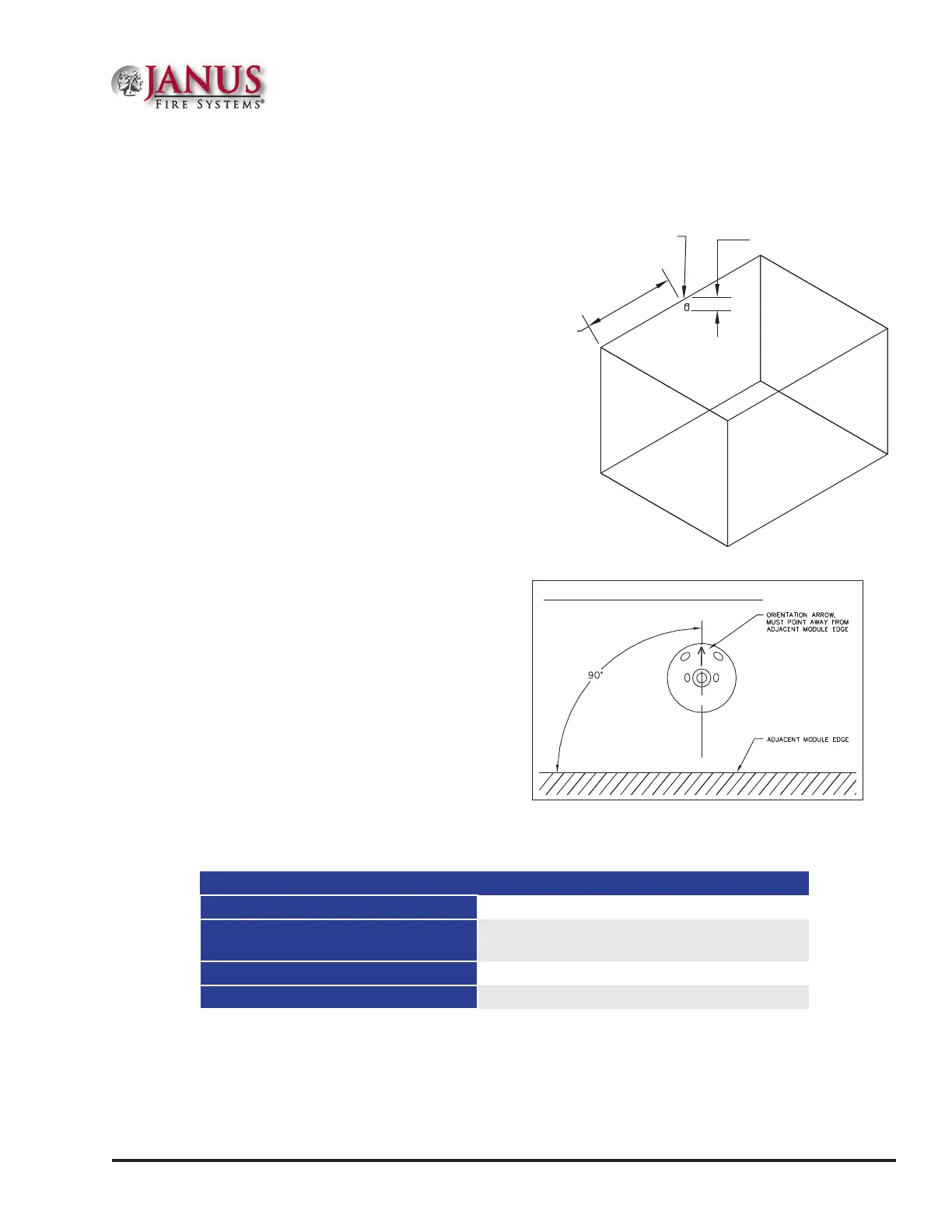
TFP NOZZLE AS VIEWED DIRECTLY FROM BELOW:
Figure 3.2.4.2a Nozzle Placement for Total Flood Perimeter
Figure 3.2.4.2b Total Flood Perimeter Nozzle Top View
Table 3.2.4.2.1 TFP Nozzle Coverages
Maximum Module Volume 2,720 ft³ (77.02 m³) per Nozzle
Maximum Module Area
217.6 ft² (20.21 m²) per nozzle at 12.5 ft
(3810 mm) nozzle height
Maximum Module Height 12.5 ft (3810 mm)
Maximum Module Side Length 16 ft (4877 mm) either dimension
3.2.4.2 Total Flood - Module Perimeter Coverage
3.2.4.2.1 Nozzle Orientation
e Total Flood Perimeter (TFP) Nozzle,
(P/N 17809) is used to provide application of
extinguishing agent from the upper perimeter of
the module being protected. e nozzle is to be
installed through the top of the module, at the
closest point to the intersection of the module
wall and module top. e nozzle location,
laterally, is to be at the midpoint of the adjacent
module edge. [e nozzle may be offset laterally
(side to side) from the midpoint as long as the
maximum lateral horizontal distance from the
nozzle to the module edge does not exceed 8 ft
(2438 mm)] e tip of the nozzle must be within
6 in (152 mm) of its entry point. e nozzle
is to be installed vertically, with the orifices
pointing downward, and the engraved arrow
pointing into the protected module. e arrow
must be aligned perpendicular to the adjacent
wall, when viewed directly from below. Refer to
Figure 3.2.4.2a and 3.2.4.2b for proper nozzle
placement. e nozzle coverages are shown in
Table 3.2.4.2.1.
NOTE: e Janus Fire Systems® Engineered
Dry Chemical System has not been evaluated
by Underwriters Laboratories, Inc. with
respect to the total flood protection of hazards
incorporating unclosable openings exceeding
5% of the total hazard surface area.
Section 3 System Design
 Loading...