Page: 22
MV & LV SERIES ENGINEERED DRY CHEMICAL FIRE EXTINGUISHING SYSTEM
OPERATION, DESIGN, & SERVICE MANUAL
REV C
Document # DOC324
Issued: April 26, 2018
Revised: March 22, 2022
UL FILE # EX27541
2.4 Explosion-Proof Actuation Components
e following components are used in conjunction with or in place of standard components to allow
installation of cylinders in potentially hazardous areas.
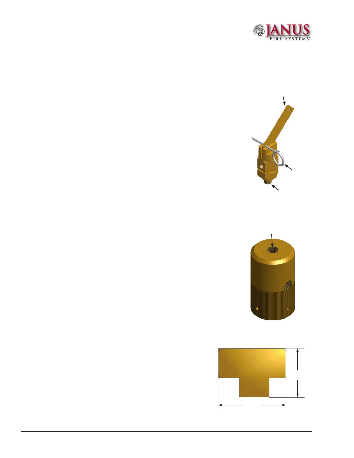
2.4.1 Lever-Pull Manual Actuator
P/N 19589 (See Figure 2.4.1)
In an explosion-proof arrangement, the lever-pull manual actuator is installed
via the manual/pneumatic actuator onto the remote nitrogen pilot cylinder
located within the hazardous area.
2.4.2 Manual/Pneumatic Actuator
P/N 98533 (See Figure 2.4.2)
In an explosion-proof arrangement, the manual/pneumatic actuator
is installed onto the remote nitrogen pilot cylinder located within the
hazardous area to facilitate the installation of the lever-pull manual actuator.
2.4.3 Remote Pilot Actuation Tee
P/N 99894 (See Figure 2.4.3)
e remote pilot actuation tee is utilized when multiple
remote pilot actuation cylinders are employed such as in an
explosion-proof arrangement. It is brass with 1/4 in (8 mm)
FNPT connections.
Figure 2.4.1 Lever-Pull Manual
Actuator
Emergency
Release Lever
Ring Pin
Threaded Valve
Connection Port
Figure 2.4.2 Manual-
Pneumatic Actuator
Manual Valve
Actuator
Connection Port
1.12 in
28.4 mm
1.56 in
39.6 mm
Figure 2.4.3 Remote Pilot Actuation Tee
Section 2 System Components and Description
 Loading...