INDOOR UNITS
3-2
TC-15001-rev.3
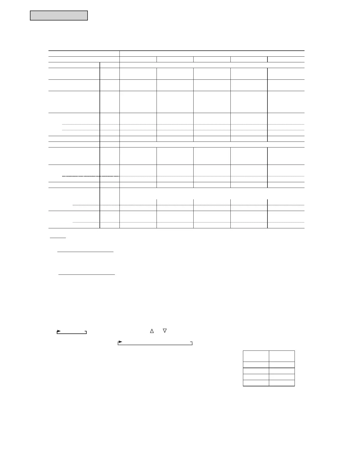
3.1.3 Ducted High Static
3.1.3.1 General Data
NOTES:
*1. Nominal capacity is based on combinations within the VRF system under the following conditions:
Cooling Operation Conditions
Indoor Air Inlet Temperature: 80°F DB (26.7°C DB)
67°F WB (19.4°C WB)
Outdoor Air Inlet Temperature: 95°F DB (35.0°C DB)
Heating Operation Conditions
Indoor Air Inlet Temperature: 70°F DB (21.1°C DB)
Outdoor Air Inlet Temperature: 47°F DB (8.3°C DB)
43°F WB (6.1°C WB)
Piping Length: 24 ft. 7-3/16 in. (7.5m) Piping Lift: 0ft. (0m)
*2. The sound pressure level is based on the following conditions.
4.9 ft. (1.5m) beneath the units.
7KHDERYHGDWDZDVPHDVXUHGLQDQDQHFKRLFFKDPEHUVRWKDWUHÀHFWHGVRXQGVKRXOGEHWDNHQLQWRFRQVLGHUDWLRQLQWKH¿HOG
*3. For the (H,Y)IDH series, the fan speeds are only “High” and “Low”. Therefore, the fan speed indication of the LCD is changed as
+LJKĺ/RZE\SUHVVLQJWKHIDQVSHHGNH\³
” or “ ”.
If one wired controller is connected to multiple indoor units (included with 3 or 4 taps speed of the indoor unit), the fan speed
LQGLFDWLRQRI/&'LVFKDQJHGDV+LJKĺ+LJKĺ0HGLXPĺ/RZ+RZHYHUWKHDFWXDOIDQVSHHGLVDVVKRZQLQWKHWDEOH
below.
LCD
Indication
Actual Fan
Speed
High 2 High
High High
Medium High
Low Low
,QGRRU8QLW7\SH 'XFWHG+LJK6WDWLF
0RGHO +<,'+%6 +<,'+%6 +<,'+%6 +<,'+%6 +<,'+%6
,QGRRU8QLW3RZHU6XSSO\ $&3KDVH9+]
1RPLQDO&RROLQJ&DSDFLW\ %WXK
N:
1RPLQDO+HDWLQJ&DSDFLW\ %WXK
N:
G%
2XWHU'LPHQVLRQV
+HLJKW LQPP
:LGWK LQPP
'HSWK LQPP
1HW:HLJKW OEVNJ
5HIULJHUDQW
,QGRRU)DQ
$LUIORZ5DWH FIP
+L/R
P
PLQ
᧤
([WHUQDO3UHVVXUH9
+LJK3UHVVXUH
LQ:*3D
6WDQGDUG
LQ:*3D
0RWRU1RPLQDO2XWSXW :
&RQQHFWLRQV
5HIULJHUDQW3LSLQJ
/LTXLG/LQH LQPP
*DV/LQH LQPP
&RQGHQVDWH'UDLQ 93 93
2' LQPP
,' LQPP
93 93 93
5$
)ODUH1XW&RQQHFWLRQZLWK)ODUH1XWV
6RXQG3UHVVXUH/HYHO
2YHUDOO$6FDOH
>)DQ6SHHG+L/R9
)DQ6SHHG+L/R9@
 Loading...
