INDOOR UNITS
3-78
TC-15001-rev.3
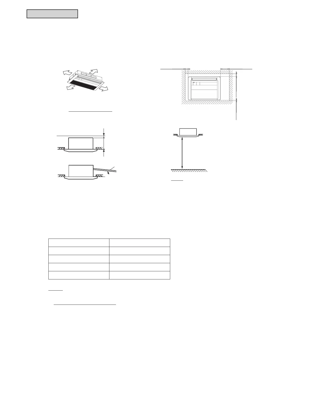
3.3.7 Operation Space
3.3.8 Sensible Heat Factor (SHF)
Models: (H,Y)IC1006B21S, (H,Y)IC1008B21S, (H,Y)IC1012B21S and (H,Y)IC1015B21S
Min.
59-1/16 (1500)
Min.
3-15/16 (100)
Min.
25/32 (20)
Min.
11-13/16 (300)
Piping Side
Distance from Wall
Min. 3-15/16
(100)
Min. 11-13/16
(300)
Unit: inch (mm)
Min.3-15/16
(100)
Min. 25/32
(20)
< For One Unit Installation >
Min. 94-1/2
(2400)
Floor Level
NOTE:
This figure indicates the minimum service space.
There are no obstacles which may hamper
incoming and discharged air.
(Unit Height in False Ceiling)
Clearance
Down Slope
Gradient: 1/25 to 1/100
Condensate Piping
9-1/4 (235)
Min. 13/32 (10)
Model SHF*1
(H,Y)IC1006B21S 0.79
(H,Y)IC1008B21S 0.80
(H,Y)IC1012B21S 0.83
(H,Y)IC1015B21S 0.83
NOTE:
1. SHF is based on combinations within the VRF system and the following conditions:
Cooling Operation Conditions
Indoor Air Inlet Temperature: 80
o
F DB (26.7
o
C DB)
67
o
F WB (19.4
o
C WB)
Outdoor Air Inlet Temperature: 95
o
F DB (35.0
o
C DB)
Piping Length: 24 ft. 10-13/16 in. (7.5m)
Piping Lift: 0 ft. (0m)
 Loading...
