CONTROL SYSTEM
TC-15001-rev.3
6-61
* Turn OFF the power supply when setting the DIP switches and rotary switch.
Do not touch the printed circuit board and metal part to avoid a mini central controller malfunction.
$ODUPZLOOEHGLVSOD\HGRQDQ+/,1.,,FRPSOLDQWFHQWUDOFRQWUROOHULIDPLVFRQ¿JXUHG'6:
is connected. In this case, turn OFF the power supply for all central control devices and correct the
settings of each central control device. Then, restart central control devices.
:KHQXVLQJVHYHUDOPLQLFHQWUDOFRQWUROOHUDWWKHVDPHWLPHVHW³56:´VRDVQRWWRRYHUODS
Switch settings of the mini central controller are indicated in the following table.
1) Use the settings below.
Switch
Switch
No.
Usage
Factory
Setting
5HPDUNV
RSW1
(Rotary
Switch 16-
pole)
- For address setting of mini central controller 0 When using multiple units.
DSW1
(DIP Switch
4-pole)
1 OFF (Fixed) OFF
2 OFF (Fixed) OFF Not Used
3 OFF (Fixed) OFF Not Used
4 ON (Fixed) ON
DSW2
(DIP Switch
2-pole)
1 21 7HUPLQDWLQJ5HVLVWDQFH(QDEOH
OFF: Terminating Resistance Disable
OFF 0DNHVXUHQRRWKHU
terminating resistance exists
on the same H-LINK when
enabling the terminating
resistance from the mini
central controller.
2 ON: Protection Fuse for H-LINK ... Disable
(short-circuited)
2))3URWHFWLRQ)XVHIRU+/,1.(QDEOH
(normal)
OFF
SW1 ON: Turn ON Mini Central Controller
OFF: Turn OFF Mini Central Controller
ON
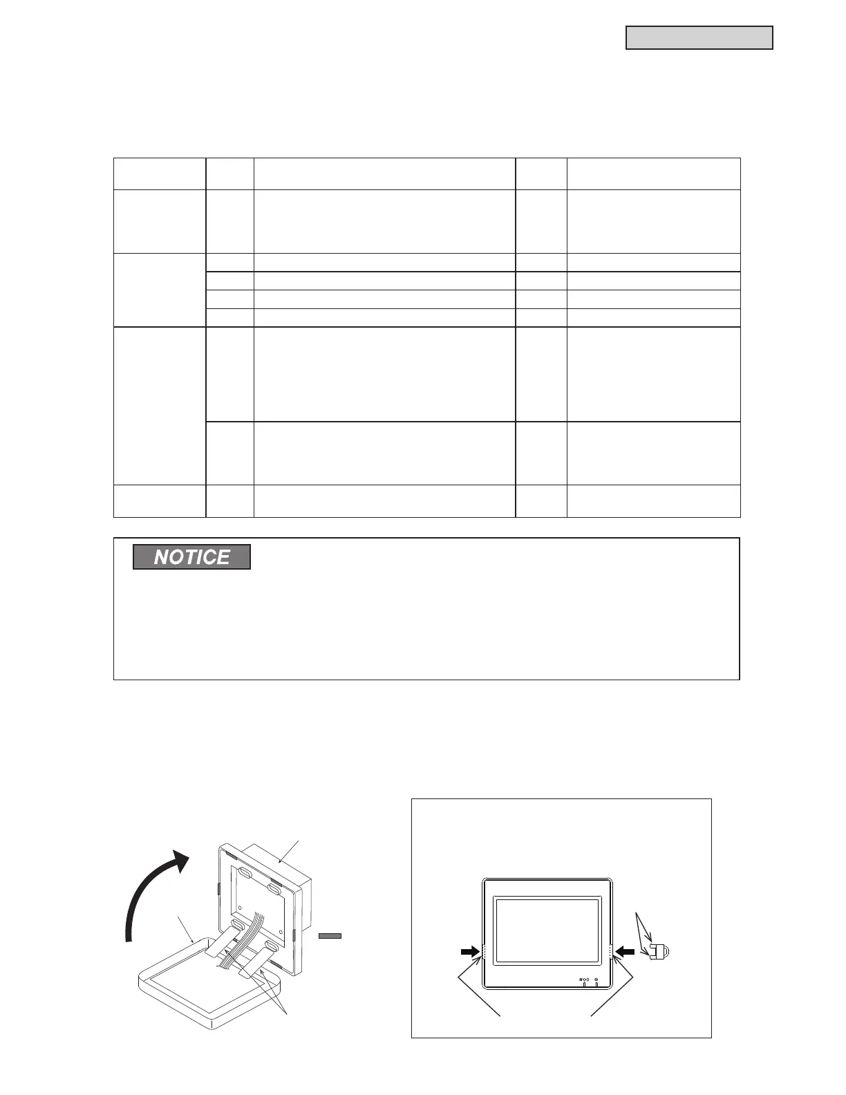
&ORVHWKHXQLWERG\XQWLOLWVQDSVPDNLQJVXUHLWLVFRPSOHWHO\FORVHG
0DNHVXUHWKHFRQQHFWLRQZLULQJLVQRWFDXJKWEHWZHHQWKHFDVHWRSDQGERWWRP
D+RRNWKHFRSSHUWRWKHXSSHUVLGHRIWKHFDVH
(b) The upper side of the case will close when placing the copper of the lateral and lower side.
6.8.8 Switch Setting Procedures
Ɣ
To Attach Touch Pen Holder
When attaching the touch pen holder to the
controller, insert the copper into mounting holes
RIWKHPDLQKROGHUXQWLOKHDULQJFOLFNLQJVRXQG
: Catch for
Fixing
Connection Band
Lower Case
Upper Case
Copper
Hole for Touch Pen Holder
Latch
for closing
(Six Catches)
 Loading...
