CONTROL SYSTEM
6-62
TC-15001-rev.3
7KHPLQLFHQWUDOFRQWUROOHUUHTXLUHVZLULQJZRUNRIWKHSRZHUVXSSO\FDEOHDLUFRQGLWLRQHUDQGFRQWURO
wiring (H-LINK).
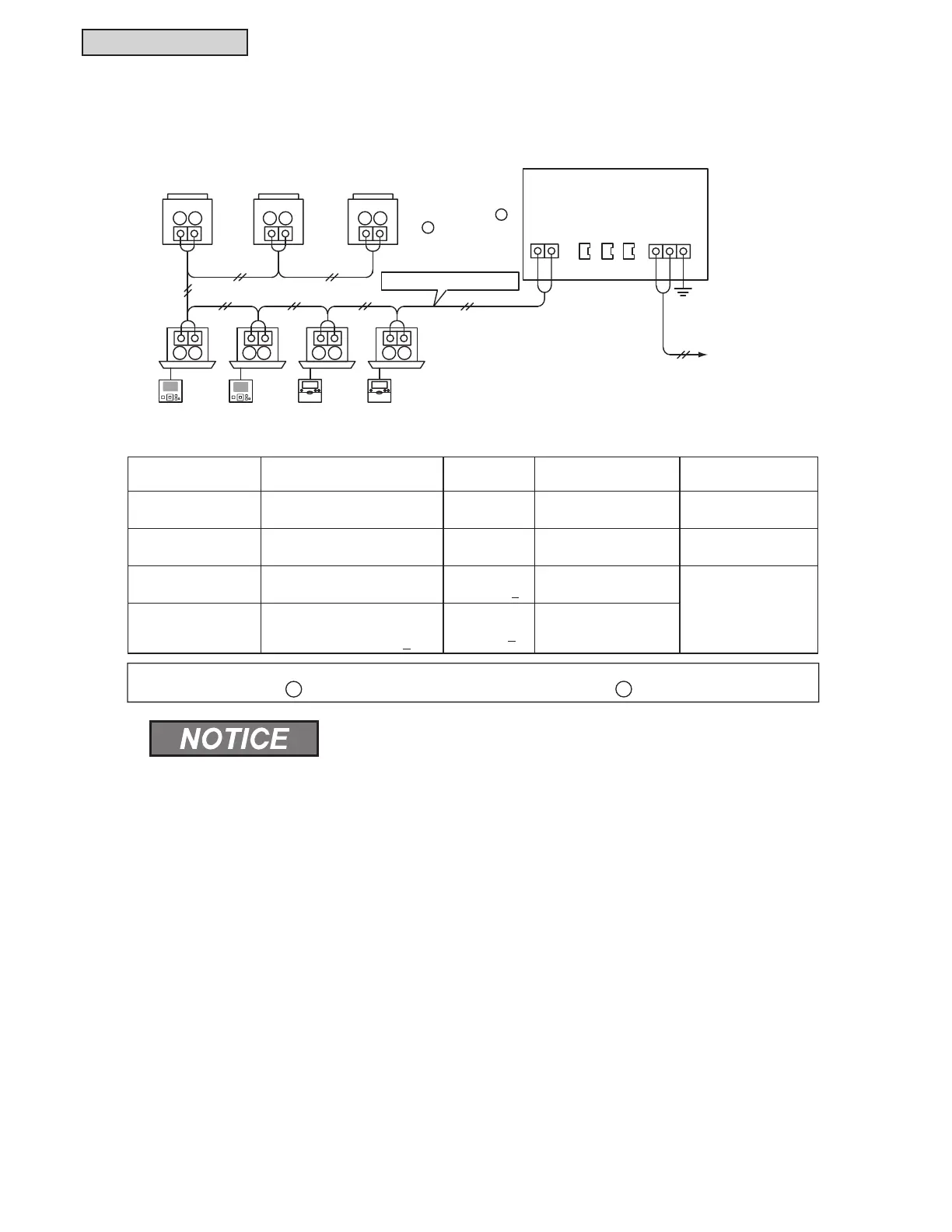
2) Wiring Method
Type of Wiring 6SHFL¿FDWLRQ
Length
of Wiring
Cable
6SHFL¿FDWLRQ
Recommended
Cable Model
Power Supply Cable 24VAC -
AWG 16(1.25mm
2
) to
AWG 14(2mm
2
)
9&9&&9&(9
Ground Wiring - - - -
H-LINK
(Control Wire)
5VDC
3281 feet
(1000m) >
AWG 18(0.75mm
2
) to
AWG 16(1.25mm
2
)
-.3(96-.(96
CVV-S, CVV,
600V VCT
:LULQJIRU([WHUQDO
Input and Output
Input:
Non-voltage Normal Open
Output: 12VDC, 75mA >
984.3 feet
(300m) >
AWG 20(0.5mm
2
) to
AWG 16(1.25mm
2
)
(OHFWULFDO:LULQJ
7KHPLQLFHQWUDOFRQWUROOHUPD\EUHDNGRZQLIZLULQJLVFRUUHFW
* Communication cabling shall be a minimum of 18-Gauge, two-conductor, stranded copper. Shielded cable
PXVWEHFRQVLGHUHGIRUDSSOLFDWLRQVDQGURXWLQJLQDUHDVRIKLJK(0,DQGRWKHUVRXUFHVRISRWHQWLDOO\H[FHVVLYH
electrical noise to reduce the potential for communication errors. When shielded cabling is applied, proper
bonding and termination of the cable shield is required as per Johnson Controls guidelines. Plenum and riser
ratings for communication
* Cables must be considered per application and local code requirements.
,IZLULQJZRUNLVSHUIRUPHGZLWKWKHPDLQSRZHU21LWPD\FDXVHDEUHDNGRZQRIWKHFRQWUROOHU
7XUQ2))WKHPDLQSRZHURIWKHDLUFRQGLWLRQHUDQGWKHFRQWUROOHUEHIRUHSHUIRUPLQJZLULQJZRUN
* Communication cables are required to be separated from the power supply wiring and other electrical device
wiring. Keep at least 12 inches (31cm) between communication cabling and the power supply wiring. If the
above is not secured, put the power supply wirings and communication cabling into the each metal conduit tube
separately. One side of the metal conduit tubes should be grounded for noise reduction.
* Do not connect the power supply wiring to the terminals for transmission of the mini central controller.
If the power supply wires are connected incorrectly, the fuse of the printed circuit board will short-circuit. If this
KDSSHQVWXUQRQWKH'6:SLQRQWKHSULQWHGFLUFXLWERDUGWRHQDEOHHPHUJHQF\RSHUDWLRQZLWKRXWEHQH¿WRI
protective fuse safeguards.
* Remove the ground wiring for the frame ground (FG) terminal when the insulating capacity test or the withstand
voltage test is performed. It may prevent operation of the mini central controller.
Power Supply
24VAC
Wired Controller
Indoor Unit
Outdoor Unit
CCM01
1
CN1
1
2
2
FG
Connect the
communication cables
to the TB terminals
and of the outdoor
units and the indoor
units.
H-LINK (Communication Cable)
Frame Ground Terminal
for Surge Absorber
Terminal
Board
TB2
Connector
Terminal
Board
TB1
1
1 1 1 1
1 1
1
2
2 2 2
2
2
2
2
CN2 CN3
• ,QFDVHZLUHOHQJWKVSHFL¿FDWLRQRQWKHVLJQDOFRPPXQLFDWLRQVLGHIRUH[WHUQDOLQSXWLVPHQWLRQHGXVH
VKRUWHUZLULQJHLWKHUFRPPXQLFDWLRQVLGHZLUHOHQJWKVSHFL¿FDWLRQRUIHHWP
 Loading...
