CONTROL SYSTEM
6-50
TC-15001-rev.3
5HYLHZWKHIROORZLQJRSWLRQDOIXQFWLRQVHWWLQJVZKHQDIXQFWLRQIRUWKH,5UHFHLYHUNLWLVVHOHFWHGIURPWKH
wireless controller or the centralized controller.
Ɣ 7KHRSWLRQDOIXQFWLRQV³&RROLQJ/RZHU/LPLWIRU6HWWLQJ7HPSHUDWXUH´DQG³+HDWLQJ8SSHU/LPLWIRU6HWWLQJ
7HPSHUDWXUH´DUHQRWDYDLODEOHZLWKWKHZLUHOHVVFRQWUROOHU
Ɣ 7KHRSWLRQDOIXQFWLRQVHWWLQJ³)L[LQJRI6HWWLQJ7HPSHUDWXUH´LVQRWDYDLODEOH:KHQWKHRSHUDWLRQPRGH
is changed from the wireless controller, the indicated temperature on the wired controller becomes the set
temperature of the wireless controller.
3
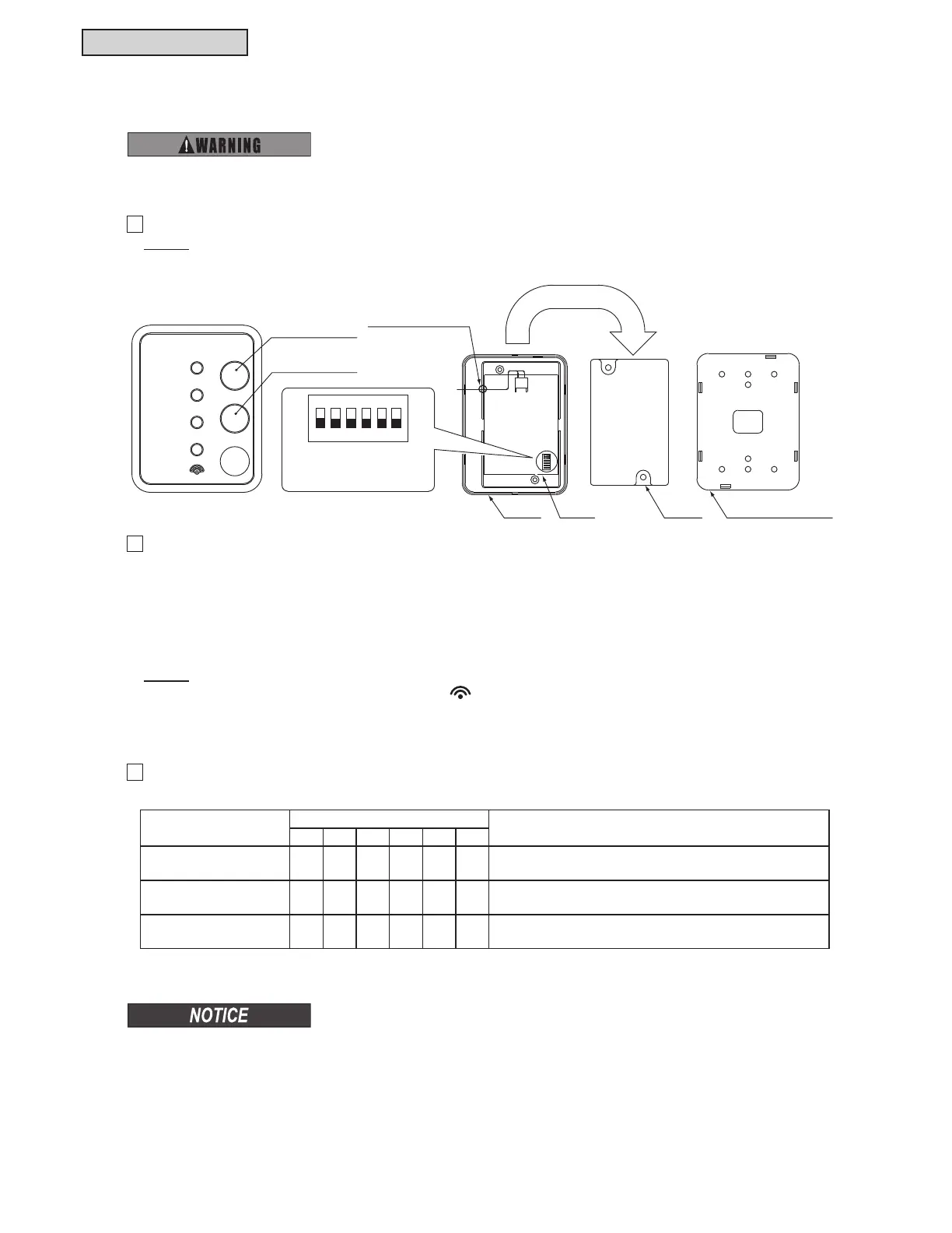
The DIP switch (DSW1) is for the optional function selection. If the optional function selection is required,
set the DIP switch as follows.
1
7KHIROORZLQJVZLWFKHVDUHRQWKH,5UHFHLYHUNLW
127(
When the case is closed, pay particular attention to the outlet position for connecting cable.
2
(PHUJHQF\2SHUDWLRQ6HWWLQJ
³&22/´DQG³+($7´VZLWFKHVDUHXVHGIRUHPHUJHQF\RSHUDWLRQZKHQWKHEDWWHULHVIRUZLUHOHVVFRQWUROOHU
are low.
6ZLWFK³&22/´3UHVV³&22/´VRWKDWWKHFRROLQJRSHUDWLRQLVVWDUWHG
3UHVV³&22/´DJDLQVRWKDWWKHFRROLQJRSHUDWLRQLVVWRSSHG
6ZLWFK³+($7´3UHVV³+($7´VRWKDWWKHKHDWLQJRSHUDWLRQLVVWDUWHG
3UHVV³+($7´DJDLQVRWKDWWKHKHDWLQJRSHUDWLRQLVVWRSSHG
127(
During an emergency operation, a yellow light “
´ÀDVKHVVHFRQG21VHFRQG2))
The temperature set-point and the fan speed for the cooling/heating operation are the same as before
starting an emergency operation.
7XUQ2))WKHSRZHUVRXUFHFRPSOHWHO\EHIRUHVHWWLQJWKH',3VZLWFKIRUDQ,5UHFHLYHUNLW
1RWGRLQJVRPD\FDXVHDQHOHFWULFVKRFN
Optional Function
DIP Switch Setting (DSW1)
Details
123456
Main/Sub Setting O X X X X X
Change main (OFF setting)/sub (ON setting) wireless
controller for a two-wireless controller system.
,GHQWL¿FDWLRQRI
Indoor Unit
XOXXXX
,WIXQFWLRQVDV%0RGHLGHQWL¿FDWLRQRILQGRRUXQLWRI
WKHZLUHOHVVFRQWUROOHUZKHQLWVHWVWR³21´
Invalidity of
(PHUJHQF\2SHUDWLRQ
X X X O X X The switches for emergency operation are invalid.
O: ON
X: OFF
6.7.8 Setting DIP Switch on IR Receiver Kit Side
3412 56
ON
RUN
DEF
FILTER
TIMER
COOL
HEAT
EMERGENCY
“COOL” Button
“HEAT” Button
Cover PCB
Outlet for
Connecting Cable
Case Mounting Bracket
DIP Switch (DSW1)
(Factory Setting)
(1) Remove the mounting
bracket.
(2) Remove two securing
screws to open the case.
 Loading...
