CONTROL SYSTEM
TC-15001-rev.3
6-49
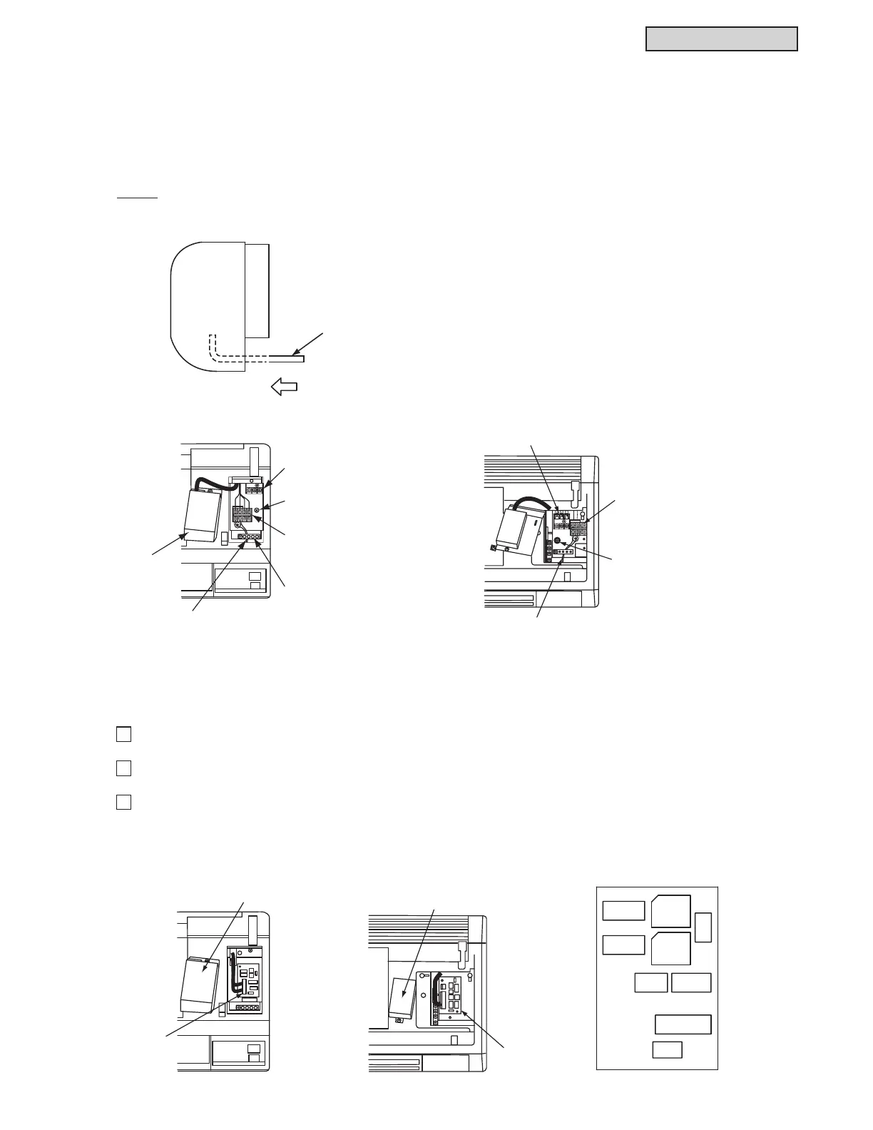
7KHWHUPLQDOEORFN7%IRUWKHFRQWUROOHUFDEOHLVORFDWHGDVVKRZQLQWKH¿JXUHEHORZ&RQQHFWWKH
FRQQHFWLQJFDEOHIRUWKH,5UHFHLYHUNLWWRWHUPLQDOV$DQG%DW7%7KHUHLVQRSRODULW\EHWZHHQWHUPLQDOV
$DQG%7KHGHWDLOVIRUZLULQJPHWKRGVFDQEHIRXQGLQWKH³,QVWDOODWLRQDQG0DLQWHQDQFH0DQXDO´IRUWKH
indoor unit.
The following wiring method is an example for wall mount indoor units
127(
After running the connecting cable, clamp the extra length of the connecting cable using the accessory
plastic band and place it in the electrical box.
Instructions for setting DIP switches for other indoor units can be found in the Installation and Maintenance
Manual for indoor units. The following DIP switch setting is an example for wall mount indoor units.
1
7KHIDFWRU\VHWWLQJRI6:EHIRUHVKLSPHQWLV³:LUHOHVV´:KHQXVLQJDQ,5UHFHLYHUNLW&:',5.VHW
WKH6:WR³:LUHG´,IQRWGRLQJVRWKHRSHUDWLRQLVQRWDYDLODEOH
2
Turn OFF the power source of the indoor and outdoor units completely before setting the DIP switch.
If not turning off the power, the setting becomes invalid.
3
The positions of the DIP switches are shown below.
Open the switch cover. After the DIP switch is set, re-attach the switch cover. The details for setting DIP
switches for an indoor unit can be found in the Installation and Maintenance Manual for indoor units.
< TIWM006 - 012B21S > < TIWM015 - 024B21S >
< TIWM006 - 012B21S > < TIWM015 - 024B21S > < DIP Switch PCB (PCB2) >
Insert the connecting
cable from the rear
side of indoor unit.
Switch Cover
PCB
2
Switch Cover
PCB2
DSW5
RSW2
RSW1
DSW6
DSW9 DSW2
SW1
SW2
DSW3
(OHFWULFDO:LULQJ
6.7.7 Setting DIP Switches on Indoor Unit Side
A 12
Electrical Box
Cover
Terminal Block for
Power Source (TB1)
Screw for
Ground Wiring Connection
Connecting Cable
for IR Receiver Kit
Fix the wires with
cable clamp.
Terminal Block for
Controller Cable (TB2)
Terminal Block for Power Source (TB1)
Screw for
Ground Wiring Connection
Connecting Cable
for IR Receiver Kit
Terminal Block for
Controller Cable (TB2)
AB1
 Loading...
