CONTROL SYSTEM
6-10
TC-15001-rev.3
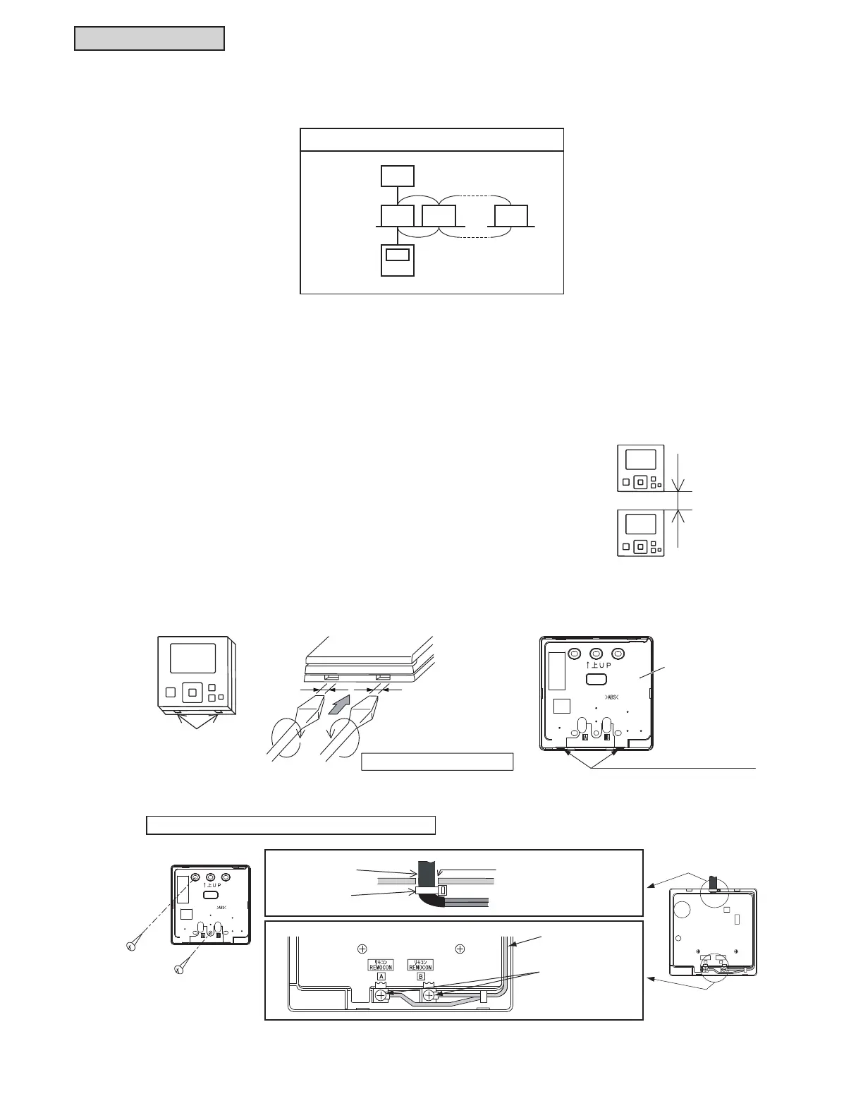
$:KHQ([SRVLQJ&RQWUROOHU&DEOH
$WWDFKWKHFRQWUROOHUWRWKHKROGLQJEUDFNHWDQGFRQQHFWWKHFDEOHDVIROORZV
6.2.6.3 Installation Procedures
,QVHUWWKHHGJHRIWKHVORWWHGVFUHZGULYHULQWRWKHJURRYHDWWKHERWWRPRIWKHKROGLQJEUDFNHWSXVKDQG
WXUQWKHVORWWHGVFUHZGULYHUDQGWKHQUHPRYHWKHFRQWUROOHUIURPWKHKROGLQJEUDFNHW
Groove Part
Figure Seen from Bottom Side
Slotted
Screw Driver
Approx. 15/64 inch
(6mm)
Groove for Attaching Controller
Rear Cover
Band Stopper
(Field-Supplied)
Cable
Attach the stopper (plastic band)
to the cable at the inside of
the draw-out hole.
Draw-out Hole
Lead the cable with its
sheath peeled through
the groove.
Peel the insulation at
the end of the cable and
clamp the M3 solderless
terminals (field-supplied).
Fix the holding bracket
onto the wall with
screws (accessory).
6.2.6.1 Selection of Installation Location
1) With the customer’s approval, determine a suitable installation location for the controller. Do not install
the remote control switch in the following places:
ƔZKHUHFKLOGUHQFDQWRXFK
ƔZKHUHWKHDLUIURPWKHDLUFRQGLWLRQHULVGLUHFWO\GLVFKDUJHG
6.2.6.2 Before Installation
7KLVSDFNLQJFRQWDLQVWKHIROORZLQJSDUWV
[A] Wired Controller (Qty: One for operation control)
>%@ 6FUHZ0[/!4W\7ZRIRULQVWDOOLQJWKHKROGLQJEUDFNHWRQWRWKHZDOO
[C] Operation Manual (Qty: One)
6.2.6 Installation
One controller can control up to 16 units.
With Communication Cable
1
12 N
Indoor Unit
N = 16 (Max.)
More than
2 Inches
(51mm)
 Loading...
