CONTROL SYSTEM
TC-15001-rev.3
6-59
6.8.7.3 Preparation at the Site
Before installing a controller, prepare the following items.
Parts 6SHFL¿FDWLRQ
Steel Box Option
Power Supply
Cable
&DEOH63(&$:*PP
2
) to AWG 14(2mm
2
)
5HFRPPHQGHG&DEOH9&9&&9&(9
H-LINK Cable
(For Control)
&DEOH63(&$:*PP
2
) to AWG 16(1.25mm
2
)
5HFRPPHQGHG&DEOH-.(396-.(96&996&9999&7
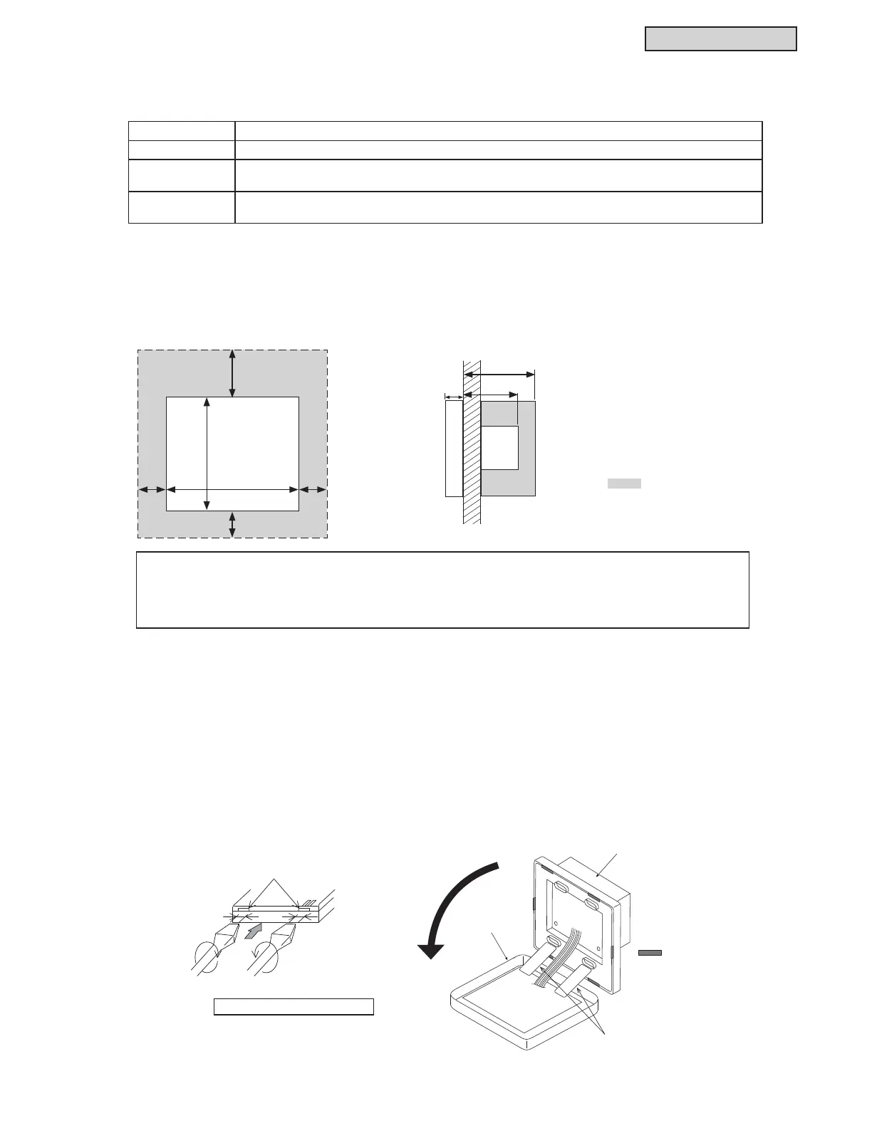
[Installation Space]
Provide the installation space for the mini central controller as shown below.
[Installation Method]
1) Install the steel box (option) into the wall.
2) Open the unit body. (The factory ships the unit open.)
If the unit is closed, open it as shown below.
(a) Remove the convex part of the case by pressing and rotating a screwdriver in the cut-out portions (two
cut-out portions on the convex part).
(b) When pulling up the convex part of the case, the copper will separate from the upper side and
ODWHUDOVLGHVRWKHFRYHUZLOORSHQ7KHXSSHUDQGORZHUFDVHZLOOEH¿[HGZLWKDFRQQHFWLRQEDQG
Do not use excessive force to open the case.
Note: Communication cabling shall be a minimum of 18-Gauge, 2-Conductor, Stranded Copper. Shielded cable
PXVWEHFRQVLGHUHGIRUDSSOLFDWLRQVDQGURXWLQJLQDUHDVRIKLJK(0,DQGRWKHUVRXUFHVRISRWHQWLDOO\H[FHVVLYH
electrical noise to reduce the potential for communication errors. When shielded cabling is applied, proper bonding
and termination of the cable shield is required as per Johnson Controls guidelines. Plenum and riser ratings for
communication cables must be considered per application and local code requirements.
:KHQLQVWDOOLQJPRUHWKDQWZRPLQLFHQWUDOFRQWUROOHUVLQDURZRULQOLQHNHHSWKHVSDFHEHWZHHQHDFK
Ɠ Vertical Direction: 2 inches (51mm)
Ɠ Horizontal Direction: 1-3/16 inch (30mm)
Unit: inch (mm)
7/8
(22)
2-3/32 (53)
2-3/4(70)
2(51)
4-9/16
(120)
5-9/16 (141)
1-3/16
(30)
1-3/16
(30)
1-3/16(30)
Do not attach anything
in the shaded screen
area “
´
Convex Part
Approximately
1 inch (6mm)
Slotted Screw Driver
View from Lower Side
: Latch fo
Closing
Connection Band
Lower Case
Upper Case
 Loading...
