108
Hardware Installation—Installing the
IFC-1010/2020
UL Fire Protective Signaling System Listed
N40
printer employing
EIA-232 serial interface.
UL Fire Protective Signaling System Listed terminal employing
EIA-232 serial interface and UL Listed protocol.
N40
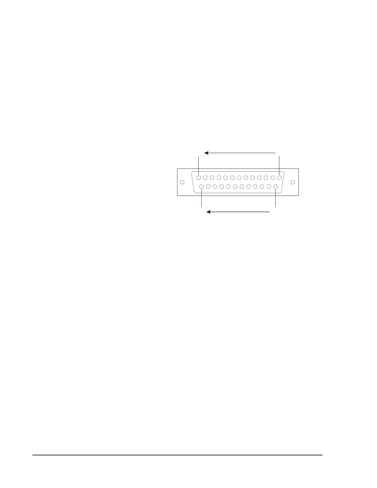
Male DB-25 connectors (Figure 77) are supplied with remote printers and
display terminals. Use these connectors to wire the interface between the
peripherals and the Serial Interface Board (SIB) as illustrated in
Figure 79, Figure 81, and Figure 82.
25
14
13 1
Male DB-25 Connector
(Solder Cup View)
db25
Figure 77: Male DB-25 Connector
Wiring to the display monitors, remote annunciators, other peripherals,
and printers must be twisted shielded pairs. Refer to Figure 78 and
Figure 79 for pair connections illustrations.
PRN Printers
CRT Terminals
Cabling and
Connections
Shield
Terminations