Hardware Installation—Installing the IFC-1010/2020
57
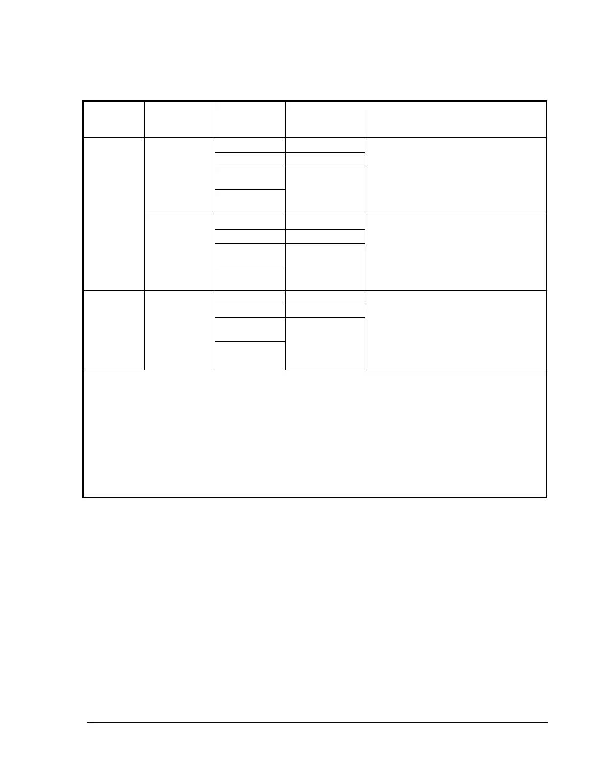
Table 9: MPS-24A or MPS-24AE Main Power Supply Loads (Regulated, Filtered
Supply)
N36
Condition Maximum
Supply Load
(All Circuits)
Maximum
Circuit Load
(Per Circuit)
Circuit Type
(See Notes)
Description
3.0 amperes Internal
1.0 ampere External 1
3.0 amperes
nonresettable
Non-Fire
Alarm with
Battery
Charger
Enabled
3.0 amperes
2.0 amperes
resettable
External 2
3 amperes of the power supply capacity
are reserved for the battery charger when
enabled. The remaining 3 ampere capacity
can be shared between the internal and
external circuits during a non-fire alarm
condition.
3.0 amperes Internal
1.0 ampere External 1
3.0 amperes
nonresettable
Non-Fire
Alarm with
Battery
Charger
Disabled*
6.0 amperes
2.0 amperes
resettable
External 2
When the internal MPS-24A/E battery
charger is not used, the full 6 ampere
capacity of the power supply can be shared
between the internal and external circuits
for up to one hour (4 amperes
continuously).
3.0 amperes Internal
1.0 ampere External 1
3.0 amperes
nonresettable
Fire Alarm
6.0 amperes
2.0 amperes
resettable
External 2
During a fire alarm condition, the battery
charger is automatically disabled, which
makes the full 6 ampere capacity of the
power supply available to be shared
between the internal and external output
circuits for up to one hour
(4 amperes continuously.)
N21
Notes: *JP1 must be cut to install either a NR45-24/E remote battery charger and disable either the MPS-24A/E
internal charger.
N22
Internal This power is used for internal requirements modules, boards, etc.
Connection: Power harness from MPS-24A/E P2 or P4 to the CPU.
External 1 Provides resettable power to 4-wire smoke detectors (and power supervision relays).
Connection: TB3 1 (+) and 2 (-).
External 2 Power for any 24 VDC UL-Listed device (typically notification appliances).
Connection: TB3 Terminal 3 (+) and 4 (-).
N37
Remote Battery JP1 must be cut to install either a NR45-24/E or CCHG-120 remote battery
Charger charger and disable the MPS-24A/E internal charger.