Hardware Installation—Installing the IFC-1010/2020
83
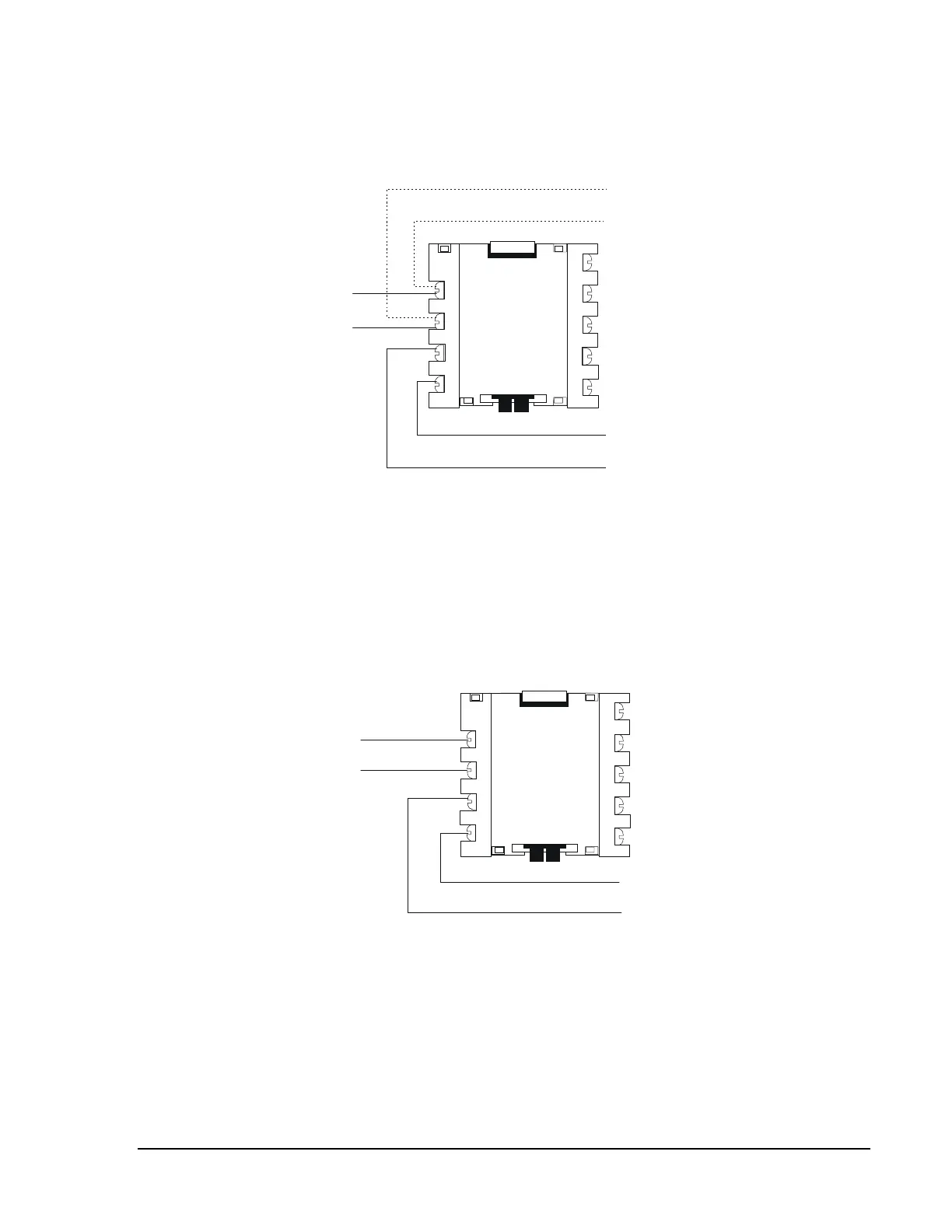
The M500XJ continuously monitors the circuit by pulsing the coil of an
integral relay, which is latched on at power up. A short circuit on the SLC
loop resets the relay (refer to Figure 56).
xj4slc1
1
2
3
4
Continuation of the Loop
SLC
Loop
T-tapped Branch Off the SLC Loop
M500XJ
Shorts on this branch of an NFPA Style 4
SLC loop will be isolated from all devices
installed both upstream of the M500XJ and
on the continuation of the main loop
(illustrated by the dotted line).
Figure 56: Isolating a Branch of a Style 4 SLC Loop
The M500XJ sees this short and disconnects the faulted branch,
effectively isolating the faulted branch from the remainder of the loop
(refer to Figure 57). Once the fault is remove, the M500XJ reapplies
power to the loop branch. Figure 55 through Figure 57 illustrate the use of
M500XJs on Style 4 SLC loops. For an example of employing M500XJs
on Style 7 (Class A) and SLC loops, refer to Figure 53.
xj4slc2
SLC
Loop
1
2
3
4
M500XJ
Remainder of the SLC Loop
Shorts on the remainder of this NFPA
Style 4 SLC loop will be isolated from
all devices installed upstream
of the M500XJ.
Figure 57: Isolating the Remainder of a Style 4 SLC Loop