86
Hardware Installation—Installing the
IFC-1010/2020
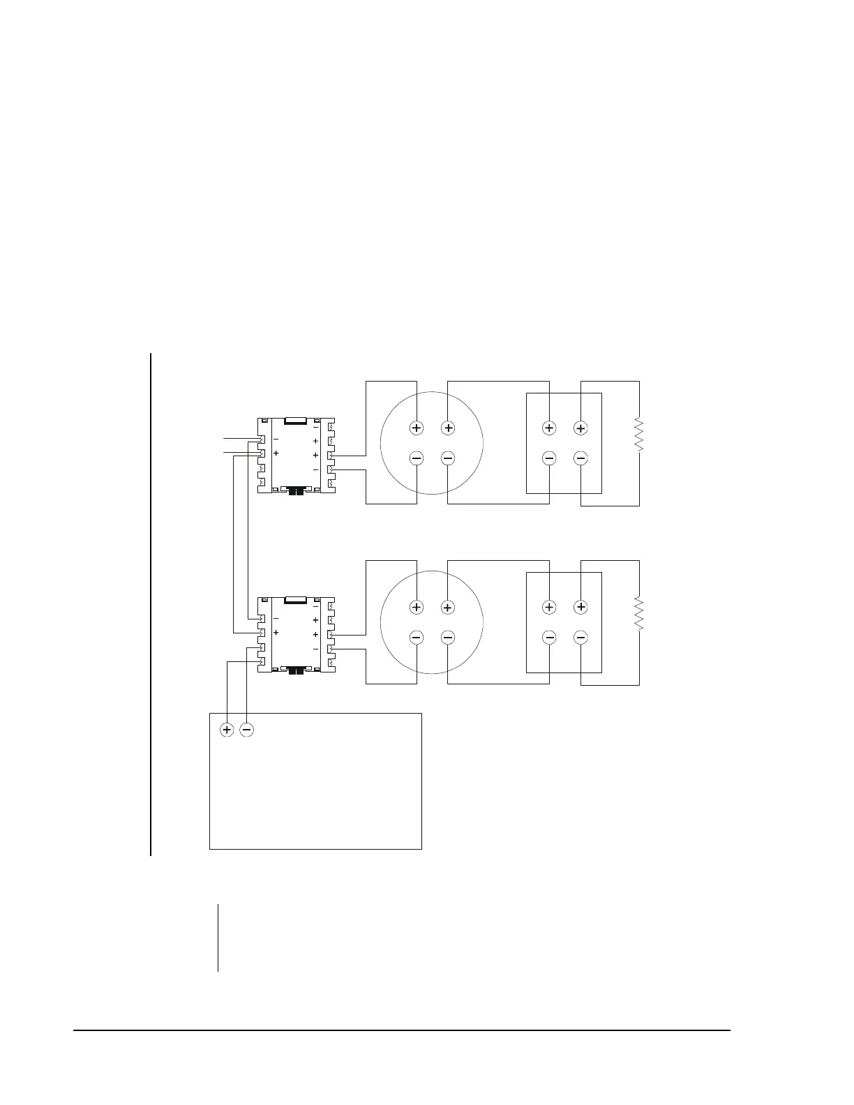
Figure 60 illustrates an M500MJ monitoring normally open contact fire
alarm initiating devices that do not require power and an M502MJ
monitoring powered two wire smoke detectors and normally open contact
alarm initiating device. Refer to Figure 62 for circuits using four wire
detectors.
Notes: For additional ratings, refer to Circuit/Device Ratings and
Connections Technical Bulletin (LIT-448160).
For connection of the initiating devices, refer to the manufacturer’s
installation instructions packaged with each device.
For more information, refer to the 500 Series Intelligent Modules
Technical Bulletin (LIT-408100).
M502MJ
1
5
2
6
3
7
4
8
9
SLC Loop Channel A
Supervised and Power-limited
M500MJ
1
5
2
6
3
7
4
8
9
LB P2-3 (-)
LB P2-1 (+)
Heat Detector Pull Station
47K End-of-Line
Resistor
(A2143-20)
3.9K Listed
End-of-Line
Resistor
SLC
24 VDC Two Wire Smoke Detectors
idcb
Power-limited
Resettable Power
UL Listed 24 VDC Regulated Power
Limited Power Supply for
Fire Protective Signaling
or
MPS-24A/E, TB3 Terminal 1 (+) and 2 (-)
APS-6R, TB2 Terminal 1 (+) and 2 (-)
Terminal 3 (+) and 4 (-)
Figure 60: NFPA Style B Initiating Device Circuit
Note: A SLC control point (M510CJ or XPR-8) with a Type ID or
PWRC is necessary to control power to the detectors to execute a
system reset when using the APS-6R. (see Figure 62).