94
Hardware Installation—Installing the
IFC-1010/2020
1
5
2
6
3
7
4
8
9
M5x0CJ
1
5
2
6
3
7
4
8
9
M5x0CJ
1
5
2
6
3
7
4
8
9
M5x0CJ
1
5
2
6
3
7
4
8
9
M5x0CJ
No end-of-line relay
required here.
No end-of-line relay
required here.
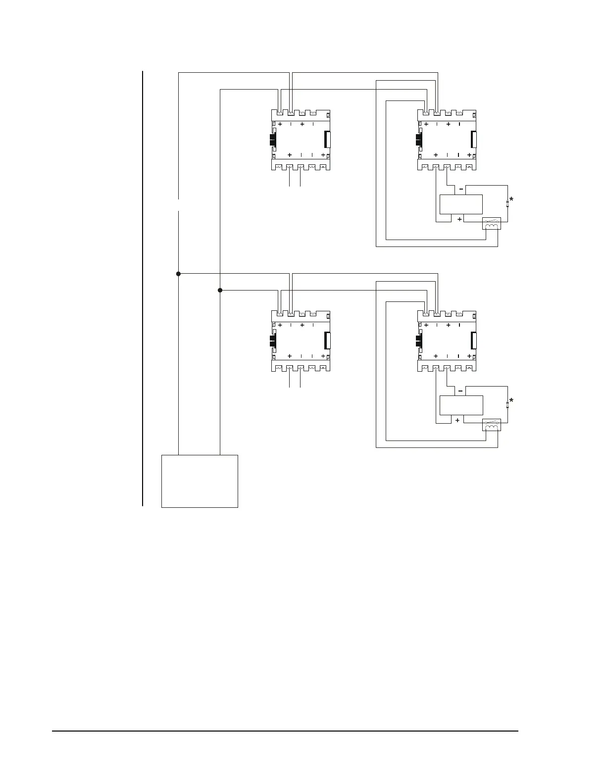
*End-of-Line Resistor,
47K, 1/2 Watt (A2143-00)
powerdis
MPS-24A/E
TB3-4 (-) TB3-3 (+)
Power-limited
Notification
Appliance
Notification
Appliance
UL Listed Power
Supervision Relay
UL Listed Power
Supervision Relay
Alarm Polarity Shown
Alarm Polarity Shown
Figure 66: Power Distribution
Note: To provide accurate supervision, the power circuit wires should be
broken at Terminals 3 and 4 of the M5x0CJ and not looped under
the terminal hold-down clamp. Any time a power circuit is
T-tapped, as seen immediately above the MPS-24A power supply,
each branch must end with a Listed power supervision relay.