Hardware Installation—Installing the IFC-1010/2020
95
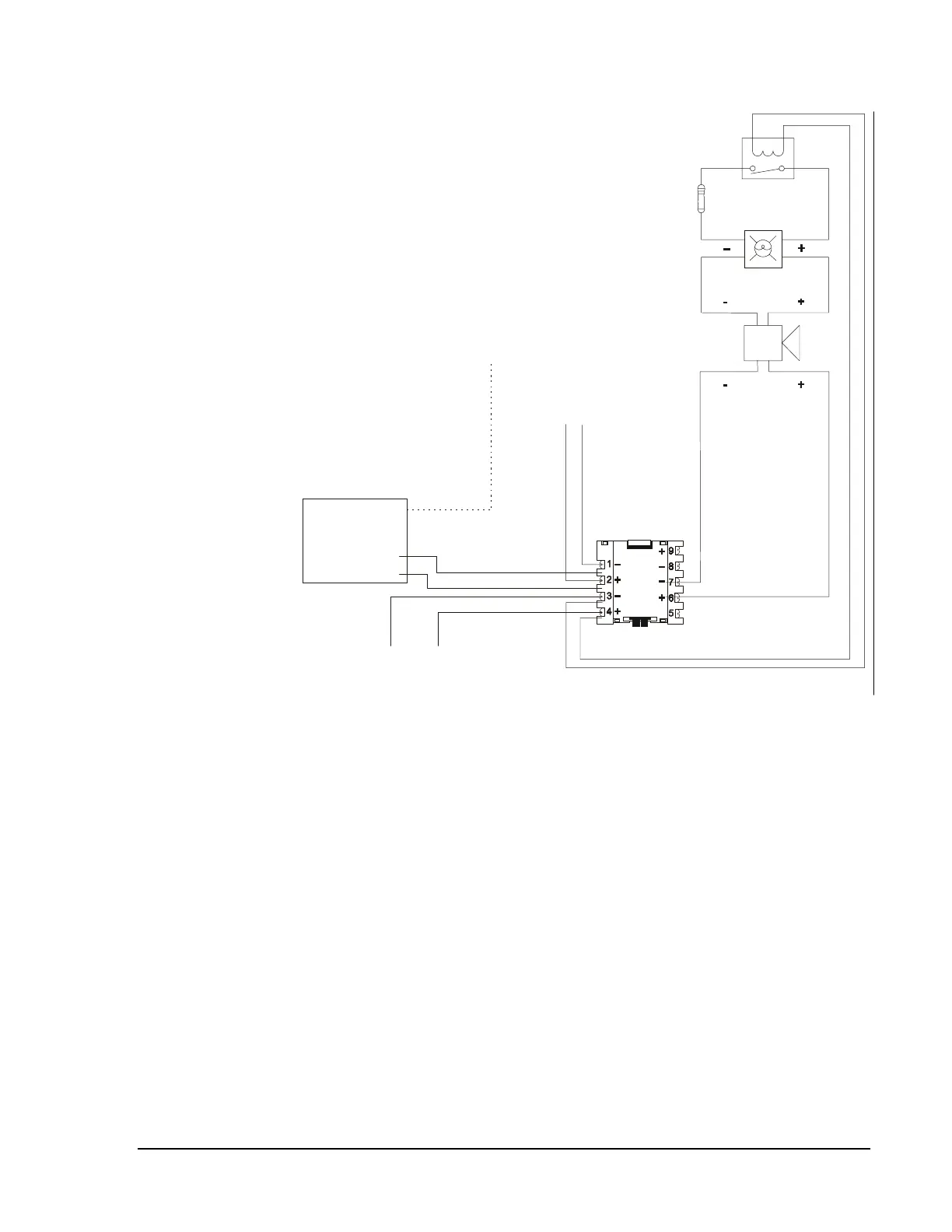
Listed Power Supervision Relay
(Contacts shown in energized position.)
47K ELR, 1/2 Watt
(A2143-20)
Alarm Polarity
Shown
LIB Channel
Terminal 3 (-)
Terminal 1 (+)
Shield Drain Wire
SLC Loop Channel A
Supervised and Power-limited
To next device on
SLC loop
Common + 24 VDC
Notification Appliance Power
This power source must be power-limited.
nfpanacy
M5x0CJ
Figure 67: NFPA Style Y Notification Appliance Circuit
Notes: To provide accurate supervision, the power circuit wires should be
broken at Terminals 3 and 4 of the M5x0CJ and not looped under
the terminal hold-down clamp. Any time a power circuit is
T-tapped, each branch must end a Listed power supervision relay.
For connection of the notification appliances, refer to the
manufacturer’s installation instructions packed with each device.
For device ratings, see Circuit/Device Ratings and Connections
Technical Bulletin (LIT-448160).