


H
Howard WhiteheadSep 9, 2025
How to clean the trackball on a JRC Monitor?
- MMaria LewisSep 9, 2025
If the trackball on your JRC monitor doesn't move smoothly, the trackball is likely dirty. Clean the trackball.
How to clean the trackball on a JRC Monitor?
If the trackball on your JRC monitor doesn't move smoothly, the trackball is likely dirty. Clean the trackball.
What to do if JRC Monitor displays 'System has detected an error'?
If your JRC Monitor displays the popup window 'System has detected an error. Turn the power off and on again,' close the popup window. Then, after ensuring it's safe to power down, turn the power off and then on again.
How to fix JRC Monitor when the power is not supplied?
If the JRC Monitor is not receiving power, check the following: * Ensure the AC or DC power supply is properly connected. * Verify the breaker at the front of the power supply unit (NBD-913) is set to ON by pushing up the lever. * Confirm the AC or DC power supply input is within the specified voltage range. If these steps don't resolve the issue, the internal wiring, the power supply unit (NBD-913), the central control unit (NDC-1590), or the operation unit (NCE-5605) may be faulty, and you should request a repair from the distributor.
What should I do if the trackball or keyboard doesn't work on my JRC Monitor?
If the trackball or option keyboard isn't working on your JRC Monitor, the internal wiring or the display unit (NCE-5605/NCE5625) may be faulty, and you should request a repair from the distributor.
Why can't I adjust the brightness on my JRC Monitor?
If you cannot adjust the brightness of your JRC Monitor, the display unit (NWZ-208/ NWZ-207/NWZ-214) may be faulty, and you should request a repair from the distributor.
Why are sensor signals not displayed on my JRC Monitor?
If sensor signals aren't displayed on your JRC Monitor, check that the communication is set correctly. Also, ensure the power supply for the sensor equipment is turned on and verify the connection with the sensor equipment, checking the LED of the corresponding port of the serial LAN interface circuit at data reception.
What to do if UPS does not operate with JRC Monitor?
If the UPS is not operating with your JRC Monitor, check the connection with the UPS and ensure it is correctly set. If the battery is extremely depleted, replace it, requesting specialized service staff for the replacement and turning off the corresponding power supply breaker in the ship during the replacement. If the issue persists, the internal wiring or the UPS itself may be faulty, requiring a repair request from the distributor.
How do I fix water depth display on my JRC Monitor?
If water depth values aren't displayed on your JRC Monitor, confirm that the communication is correctly set. Also, ensure the power supply for the echo sounder is turned on, and verify the connection with the echo sounder, checking the LED of the corresponding port of the serial LAN interface circuit at data reception.
Why is wind direction/wind speed data not showing on my JRC Monitor?
If wind direction/wind speed data isn't displayed on your JRC Monitor, first, check that the communication is correctly set. Then, ensure the power supply for the anemoscope/anemometer is turned on. Finally, verify the connection with the anemoscope/anemometer, checking the LED of the corresponding port of the serial LAN interface circuit at data reception. Also, ensure that the power supply for the serial-LAN interface circuit (CMH-2370) is turned on.
How to troubleshoot rudder angle display issues on JRC Monitor?
If the rudder angles are not displayed correctly on the JRC Monitor, verify that the communication is correctly set. Also, ensure that the power supply for the rudder angle indicator is turned on and check the connection with the rudder angle indicator, looking for the LED at data reception if connected to the serial LAN interface circuit. If connected to the serial-LAN interface circuit (CMH-2370), ensure its power supply is on.
Details hazards and precautions related to high voltages in electronic apparatus and safe handling practices.
Provides guidance on immediate actions and first aid for individuals suffering from electric shock.
Outlines the systematic steps for administering first-aid treatment to an injured person.
Lists essential safety considerations and preventive measures to be taken during first-aid procedures.
Emphasizes securing the scene and preventing further harm to individuals involved in CPR.
Describes how to assess the consciousness and responsiveness of a collapsed person.
Details the procedure for opening the airway to ensure a clear passage for breathing.
Explains how to check for the presence of breathing in an unresponsive individual.
Provides instructions on administering rescue breaths, including when it can be omitted.
Outlines the combined procedure of chest compressions and rescue breaths for CPR.
Highlights severe risks and critical safety instructions to prevent death or serious injury.
Points out potential dangers that could lead to serious injury or equipment failure if neglected.
Warns about potential minor injuries or property damage if instructions are not followed correctly.
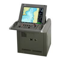
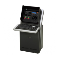
Identifies and explains the primary functions of the main operation unit components.
Identifies and describes the main elements and functions presented on the Conning Display's top screen.
Provides a step-by-step guide for powering on and starting the equipment, including pre-heating procedures.
Explains how to select and start different operational modes from the task menu.
Details the functions of the trackball and its basic operations for navigating and interacting with the system.
Guides users on how to confirm, acknowledge, and handle alerts generated by the system.
Explains how to adjust the brightness levels for both the screen display and the operation unit.
Covers the Man Over Board function, used for monitoring and marking the position of a person overboard.
Provides the correct procedure for safely turning off and terminating the operation of the equipment.
Explains the different display modes available for the Conning Display and how they are presented.
Describes how to interpret the information displayed in each block on the Conning Display screen.
Provides detailed explanations for the information indicated in each specific block on the Conning Display.
Allows users to configure various screen display options and settings through dialog boxes.
Guides users on selecting and configuring alert settings within the [Alert] dialog box.
Details how to set conditions for generating Depth Below Keel alarms to prevent grounding.
Covers setting conditions for position monitor warnings and HDOP limit cautions.
Explains how to configure alert processing actions, such as reactivation and transfer to BNWAS.
Provides an overview of basic operations within the [Settings] dialog box for configuring modes.
Explains how to set the display colors and brightness levels for various modes and elements.
Covers how to assign functions to user keys and the [MULTI] dial for customized operation.
Describes how to access the Service menu, which requires a password, for installation and maintenance.
Guides users on verifying the equipment installation and performing initial settings using the [Installation] dialog.
Explains how to set the Consistent Common Reference Point (CCRP) on the ship using the [CCRP] dialog.
Details how to verify and configure serial port settings for equipment communication.
Covers how to set the ship's specific parameters, such as dimensions and performance limits.
Explains how to use the [Maintenance] dialog box for performing maintenance operations on the equipment.
Describes how to access and execute various maintenance functions through the equipment's menu system.
Guides users on selecting and confirming the appropriate sensor sources for different data inputs.
Provides general guidelines and procedures for cleaning and maintaining the equipment.
Details specific maintenance procedures for the display unit, including screen and trackball cleaning.
Outlines procedures for performing performance checks, including self-tests and component status verification.
Lists parts that require periodic replacement and their expected service life.
Explains the process for updating the equipment's software via local or remote methods.
Details the steps for updating the product's firmware.
Covers the procedures for backing up and restoring customer data using external media.
Explains the process for recovering system images in the C drive, including OS recovery and C-MAP reset.
Explains how failures can be detected through alerts and outlines initial steps for fuse inspection.
Provides a guide to troubleshooting common failures by identifying circuit blocks and model names.
Offers a systematic approach to diagnosing and resolving equipment malfunctions based on symptoms, causes, and actions.
Details the menu items for maintenance tasks, including date/time settings and system information.
Lists the menu items related to service operations, including installation, system configuration, and device installation.
| Type | Marine Radar |
|---|---|
| Power Output | 25 kW |
| Antenna Type | Slotted waveguide array |
| Power Supply | 24 V DC |
| Transmitter Frequency | 9410 MHz |
| Transmitter Peak Power | 25 kW |
| Frequency | 9410 MHz |
| Antenna Length | 6 feet (1.8 meters) |