EasyManua.ls Logo

JRC JAN-701B - User Manual

JRC JAN-701B
564 pages
Print Icon
To Next Page IconTo Next Page
Loading...
JAN-701B/901BJAN-701B/901B
INSTRUCTIONINSTRUCTION
MANUALMANUAL
ECDISECDIS

Table of Contents

Other manuals for JRC JAN-701B

Questions and Answers

  • C
    Craig FergusonAug 20, 2025
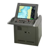
    What to do if JRC JAN-701B Marine Radar power does not turn ON?
    • C
      catherine97Aug 20, 2025
      If the JRC Marine Radar does not turn on, check the following: * Ensure the AC power is turned on. * Verify the breaker in the main unit power supply is on. * If using 220V input, confirm the input protective circuit switch of the power supply is set to AC 220V. * Make sure AC power is being input within the rated range.
  • M
    meganryanAug 22, 2025
    Why is the “GYRO” alarm displayed on my JRC Marine Radar and the gyro compass not displayed?
    • J
      Jacob WarnerAug 22, 2025
      The “GYRO” alarm and the absence of the gyro compass display on your JRC Marine Radar can be due to several reasons: * The initial setup was not carried out correctly. In this case, you should carry out the initial setup correctly. * The gyro compass is not turned on. Ensure the gyro compass is ON. * The connector cable is not connected to the gyro compass. Check the connection between the gyro compass and the main unit. * The ratio setting on the gyro compass is incorrect. Set the ratio setting on the gyro compass correctly. * The polarities of the connector cable are incorrect. Connect the cable at the correct polarities.
  • D
    Donna EverettAug 25, 2025
    What to do if “POWER FAIL” lamp is lit on JRC JAN-701B?
    • C
      Craig HansonAug 25, 2025
      If the “POWER FAIL” lamp is lit on the JRC Marine Radar, it could be due to the following reasons: * DC power is not being supplied from the distribution board. Ensure DC power is supplied from the distribution board. * The AC voltage has dropped. Input AC voltage within the rated range.
  • D
    Daniel MolinaAug 26, 2025
    What to do if nothing is displayed on the screen of my JRC JAN-701B?
    • N
      nbrooksAug 26, 2025
      If nothing is displayed on the screen of your JRC Marine Radar, verify that the power switch is turned on.
  • N
    Nicole FowlerAug 27, 2025
    Why is automatic sailing not possible on my JRC JAN-701B Marine Radar?
    • J
      Jessica StephensonAug 27, 2025
      If automatic sailing is not possible on your JRC Marine Radar, consider the following: * The initial setup has not been carried out correctly. Carry out the initial setup correctly. * The operation is not carried out correctly. Carry out the correct operation referring to the Instruction Manual. * The autopilot is not turned on. Turn the autopilot ON. * The connector cable is not connected to the autopilot. Check the connection between the autopilot and the main unit.
  • T
    Tommy McguireAug 29, 2025
    What to do if the [GAIN], [VIDEO] and [SEA/RAIN] dials do not work on JRC JAN-701B?
    • R
      Renee CookAug 30, 2025
      If the [GAIN], [VIDEO], and [SEA/RAIN] dials on your JRC Marine Radar do not work, it might be because: * The [GAIN], [VIDEO], and [SEA/RAIN] dials are not ready for operation. Press the [RADAR] key. * The knob is not secured to the shaft. Use a hexagonal wrench to secure the knob to the shaft.
  • S
    Stacey SmithAug 31, 2025
    How to fix the display if it is shown out of place on JRC Marine Radar?
    • A
      Ashlee HernandezAug 31, 2025
      If the display is shown out of place on your JRC Marine Radar: * For JAN-701, keep the brilliance control pressed for a while. The display will be adjusted automatically. * For JAN-901M, press the brilliance control. The display will be adjusted automatically.
  • K
    kellypattersonSep 2, 2025
    What to do if the trackball does not work on JRC JAN-701B?
    • C
      Colton ChangSep 2, 2025
      If the trackball on your JRC Marine Radar does not work, try cleaning the trackball.
  • B
    bryan36Sep 4, 2025
    What does it mean when JRC JAN-701B displays “FAN” alarm message?
    • P
      Patrick DixonSep 4, 2025
      If the “FAN” alarm message is displayed on the LCD monitor of your JRC Marine Radar, it means that the fan motor has stopped. Immediately turn the power OFF.
  • C
    Cindy ReynoldsSep 6, 2025
    What to do if JRC Marine Radar displays the message “CD is not inserted, or this CD might have errors. Confirm, or contact with your chart provider.” in Chart Portfolio?
    • K
      Kevin LopezSep 6, 2025
      If the message “CD is not inserted, or this CD might have errors. Confirm, or contact with your chart provider.” is displayed in Chart Portfolio, set the path correctly.

Summary

Safety Cautions

Cautions for High Voltage

Details on the dangers of high voltage and precautions to take when working with electrical apparatus.

Precautions for Rescue of Victim of Electric Shock

Steps to take when encountering a victim of electric shock, including first aid measures.

Precautions Upon Equipment Operation

1 Overview

1.1 Function

Describes the functions of the ECDIS equipment, including ECDIS and Navigation Planning capabilities.

1.2 Features

Lists the key features of the ECDIS system, covering chart display, navigation warnings, and user chart creation.

1.5 System Configuration

Illustrates an example system configuration showing how the ECDIS connects with other navigation sensors.

2 Names and Functions

2.1 Function of Operation Panel and LCD brilliance control

Details the functions of the operation panel buttons and how to control LCD brilliance.

2.2 Function of the Screen (ECDIS)

Explains the different areas of the ECDIS screen: Chart Display Area, Display Panel, and Menu Title Bar.

3 Basic Operation of ECDIS

3.1 Menu Operation

Describes how to select menus, use the trackball, and navigate through menus and submenus.

3.3 Power ON;OFF and Preparation

Details the procedure for turning the ECDIS system ON and OFF, including necessary preparations.

3.3.7 How to Release the Alarm ([ALARM ACK])

Explains how to acknowledge and release alarms, including displaying the alarm list.

3.3.9 The AIS;TT target Display

Explains how to display AIS/TT target information on the chart using operation panel or menu.

3.12 Selecting Route and To WPT

Describes how to select a route and the next waypoint for navigation.

4 Route Planning

4.1 Route Planning

Explains how to create routes using either the Table Editor or the Graphic Editor.

4.1.1 Setting the Route Options

Details the various options for setting up routes, including default values and safety checks.

5 Chart Editing

5.1 Chart Edit Mode

Introduces the two modes for chart editing: User Map Edit and Manual Update.

6 Automatic Sailing

6.1 Automatic Sailing System

Overview of the automatic sailing system and how it interacts with the autopilot.

6.2 Setting the Automatic Sailing

Details the settings for automatic sailing, including tracking gain, drift correction, and dead band.

6.3 Automatic Sailing Operation

Outlines the operational steps for ECDIS and autopilot during automatic sailing.

7 Tools and Setting;Serviceman Menu

7.10 Setting the Alarm Options

Details how to configure various alarm limits and area-related alarms.

7.21 Data Backup;Restore

Provides instructions for backing up and restoring system settings and data.

8 Playback

8.1 Entering;Exiting the Playback

Describes how to access and exit the playback function to review logged data.

8.2 Playing Back the Logging Data

Details how to set the start date/time and play back the logged navigation data.

9 Reference

9.1 Alarm Function

Provides a comprehensive list of system and navigation alarms, their meanings, and conditions.

10 Maintenance and Inspection

10.6 Troubleshooting

Provides a guide to common problems and their solutions for the ECDIS unit.

11 Operation of Multi Window

12 Display and View of Multi Window

JRC JAN-701B Specifications

General IconGeneral
BrandJRC
ModelJAN-701B
CategoryMarine Radar
LanguageEnglish

Related product manuals