– 45 –
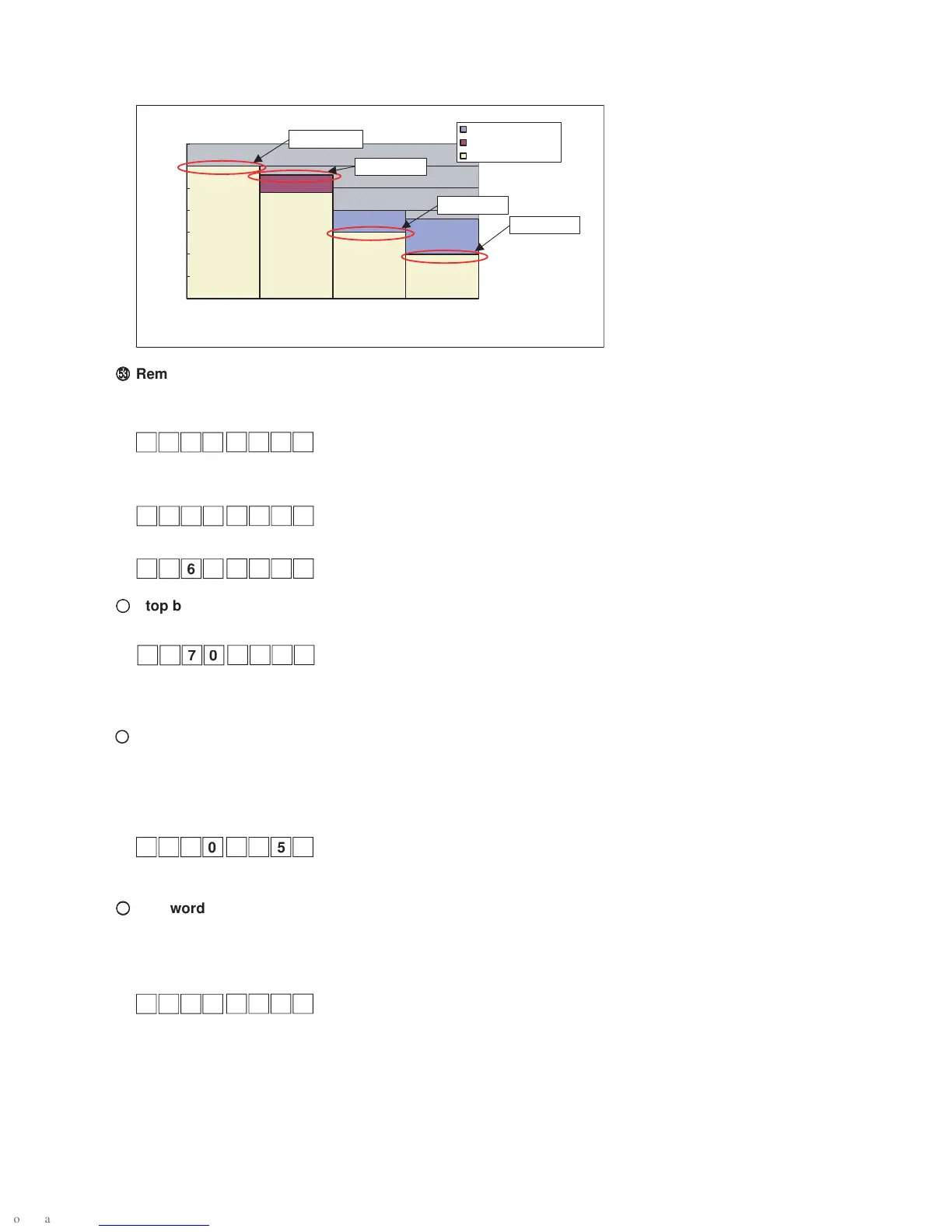
A graph of the speed limit at the settings above is displayed.
££
££
£
Remaining thread detection function (Function setting Nos. 167, 168, and 169)
The setting is performed in the case of using the remaining bobbin thread detection device.
Function setting No. 167 Remaining bobbin thread detection, enabled/disabled
0 : Disabled
1 : Enabled
Function setting No. 168 Remaining bobbin thread detection function
Refer to the instruction manual for further information on setting values.
Function setting No. 169 Time of air blow to remaining thread detection device
0 to 3000 ms Air blow time after thread trimming is specified.
¢¢
¢¢
¢
Stop brake angle setting (Function setting No. 170)
This function allows the lowering needle to stop later than the normal stop if the lowering needle stop is active.
0 : Function disabled
1 to 180 degrees Brake delayed angle
33 V switching duty setting (Function setting No. 190)
Setting of the output duty provided to the machine head supporting 24 V solenoid output (DNU-1541) is per-
formed.
(Caution) If an excessively small value is selected for this setting, malfunction or defective pitch will be
caused. Therefore, extreme caution should be exercised when the value is changed.
10% to 90%
§§
§§
§
Password lock function (Function setting No. 192)
Once this function is activated, stitching count, reverse feed stitching, and one-touch operation cannot be speci-
fied.
Password entry is required when function setting is performed.
0 : Function disabled
1 to 9999Password
0
500
1000
1500
2000
2500
3500
3000
1 to 2.5 2.5 to 4 4 to 4.75 4.75 to 6.5
DL
SPd1 :3000
SPd2 :2800
SPd3 :1500
SPd4 :1000
Speed [sti/min]
Model-specific
Set value
Decided limit value

 Loading...


