Art. No. SC 1000 KNX
o Position the decorative frame (17) on the supporting ring.
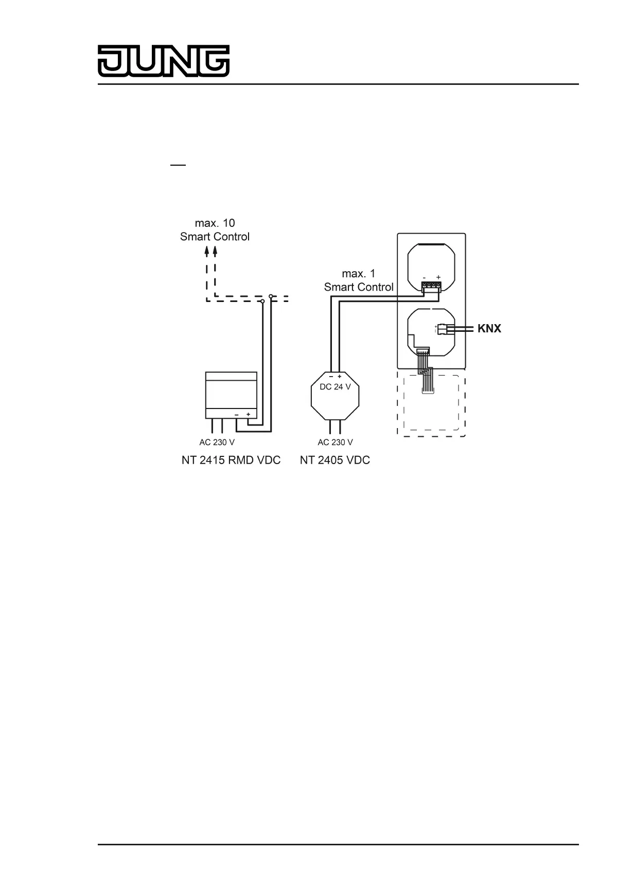
Connect the external power supply...
The Smart Control needs an external DC power supply for supplying the device electronics
(figure 4). It is not possible to use the unchoked output of KNX power supplies as device power
supply! The power supply must be provided by an additional device (e.g. RMD or UP DC power
supply) (see accessories).
Figure 4: Connecting diagram for external DC power supply
o Connect power supply to terminal (18) and insert into connection (9) (figure 2). Comply with
the polarity!
Completing installation...
o Connect the KNX bus cable to the bus connection of the communication module.
o Insert the Smart Control with the communication module carefully into the supporting frame
and lock into place. Ensure that no cables are squashed.
Page 12 of 347
Installation, electrical connection and operation
 Loading...