EX2500 Ethernet Switch Components 7
Chapter 1: EX2500 Ethernet Switch Description and Specifications
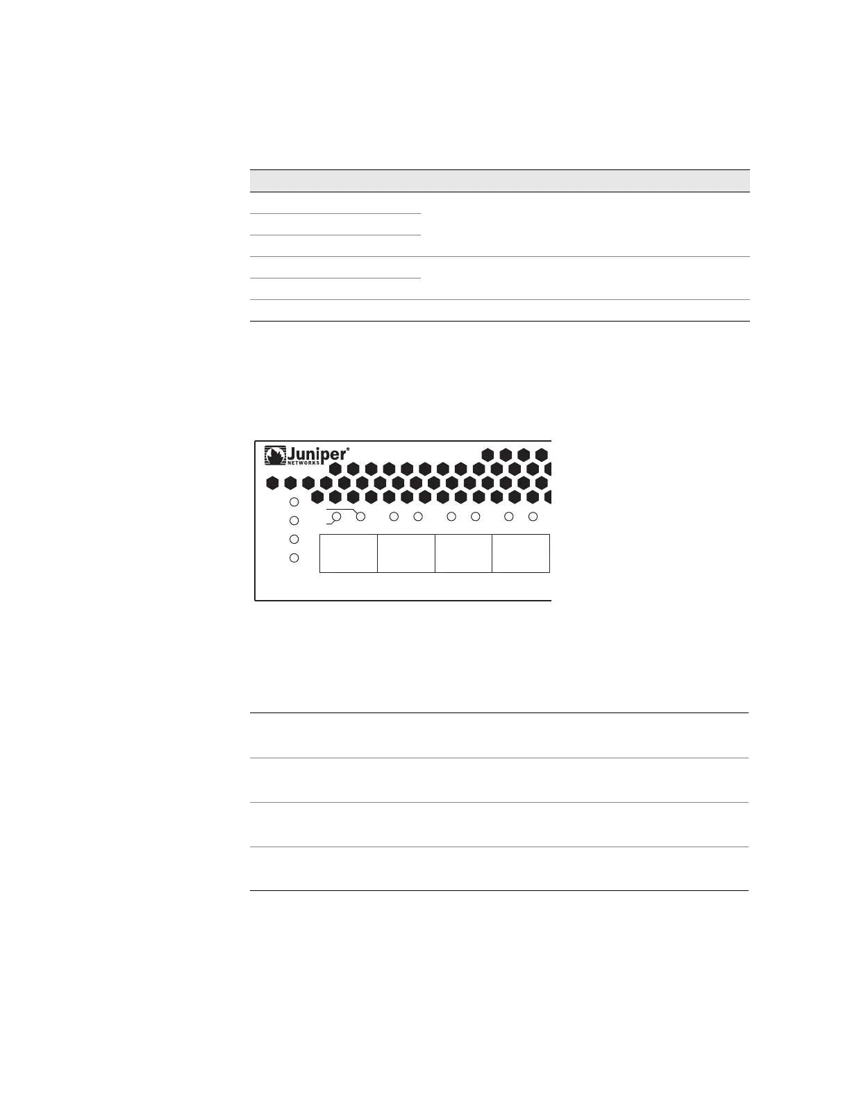
LEDs
LEDs provide system status and port link status. Figure 3 highlights the system
LEDs and SFP+ port LEDs.
Figure 3: System Status LEDs and Port LEDs
System and Fan LEDs
The system and fan LEDs are described in Table 8.
Pin 1
D9 Pins 1, 4, and 6 are connected.
Pin 4
Pin 6
Pin 7
D9 pin 7 is connected to D9 pin 8.
Pin 8
Shell Braid Shell
Table 7: Console Cable Pin Assignments (2 of 2)
D9 Pin Number Wire Mini-USB Pin Number
Table 8: System and Fan LEDs
Power supplies and AC power input status
Fans status
Status LED
Status LED (reserved for future use)
SP
L/A
ST-A
ST-B
1 2 3 4
FAN
SYS
SYS
FAN
ST-
ST-B