•
SRX1400: Slot 2. Also supported in slot 1 when installed in conjunction with a Network
Processing Card (NPC) in slot 3.
•
SRX3400: Front slots labeled 1 through 4 and rear slots labeled 5 through 7.
NOTE: For the SRX3400 Services Gateway to meet NEBS and ETSI standards, it must
not have any two SPCs installed side by side in the CFM slots in the front of the chassis
(CFM slots 1 through 4). You can install SPCs side by side in the CFM slots in the rear
of the chassis (CFM slots 5 through 7).
•
SRX3600: Front slots labeled 1 through 6 and rear slots labeled 7 through 12. We
recommend that you install SPCs in rear panel slots to leave room for IOCs in the front
panel slots.
NOTE: For the SRX3600 Services Gateway to meet NEBS and ETSI standards, it must
not have any two SPCs installed side by side in the CFM slots in the front of the chassis
(CFM slots 1 through 6). You can install SPCs side by side in the CFM slots in the rear
of the chassis (CFM slots 7 through 12).
Supported Slots
SPCs are cold-swap-only modules. You must power-off the services gateway before
removing, replacing, or adding SPCs.
Swapping
SERVICE LED, one tricolor
•
Green–The SPC is running under acceptable load.
•
Amber–The SPC is overloaded.
•
Red–No service is being provided by the SPC.
•
Off–The SPC is not enabled.
OK/FAIL LED, one bicolor:
•
Steady Green–The SPC is operating normally.
•
Blinking Green–The SPC is preparing for hot-swap event.
•
Red–The SPC has failed and is not operating normally.
•
Off–The SPC is powered down.
LEDs
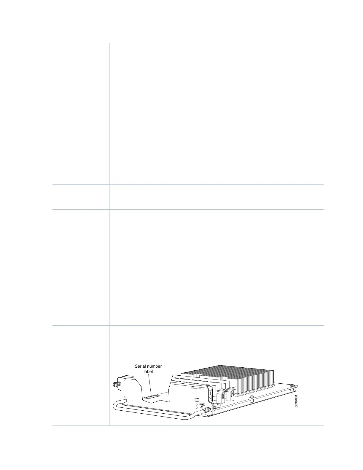
The SPC serial number label is located as shown in Figure 15 on page 33).
Figure 15: SPC Serial Number Label
g036081
S
R
X3K-SPC-1-10-40
Serial number
label
Serial Number
Location
33