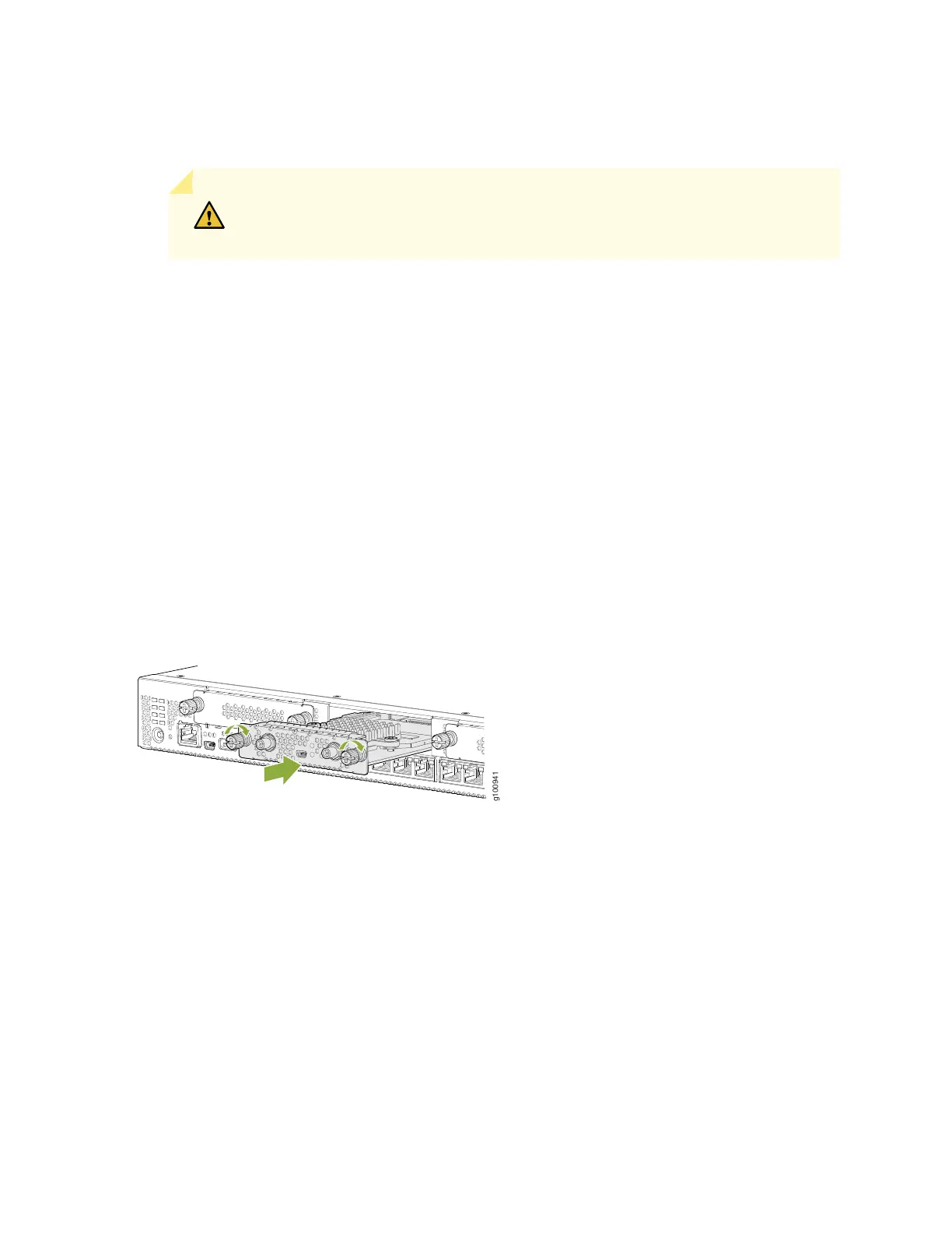
4. Grasp the screws on each side of the Mini-PIM faceplate and align the notches in the connector at the
rear of the Mini-PIM with the notches in the Mini-PIM slot in the device.
CAUTION: Slide the Mini-PIM straight into the slot to avoid damaging the
components of the Mini-PIM.
5. Slide the Mini-PIM in until it is fully seated in the services gateway.
6. Tighten the screws on each side of the Mini-PIM faceplate.
7. Insert the appropriate cables into the cable connectors on the Mini-PIM.
8. If necessary, arrange the cables to prevent them from dislodging or developing stress points:
•
Secure the cables so that they are not supporting their own weight as they hang to the floor.
•
Place any excess cables out of the way in neatly coiled loops.
•
Use fasteners to maintain the shape of the cable loops.
Figure 22: Installing a Mini-PIM in an SRX380 Device
9. Reconnect the power adapter to the services gateway. Verify that the Power LED glows steadily green
after you press the power button.
10. Verify that the Mini-PIM LED on the device chassis glows steadily green to confirm that the Mini-PIM
is online.
67