Preparations
EN I
29
Input/Output Setting
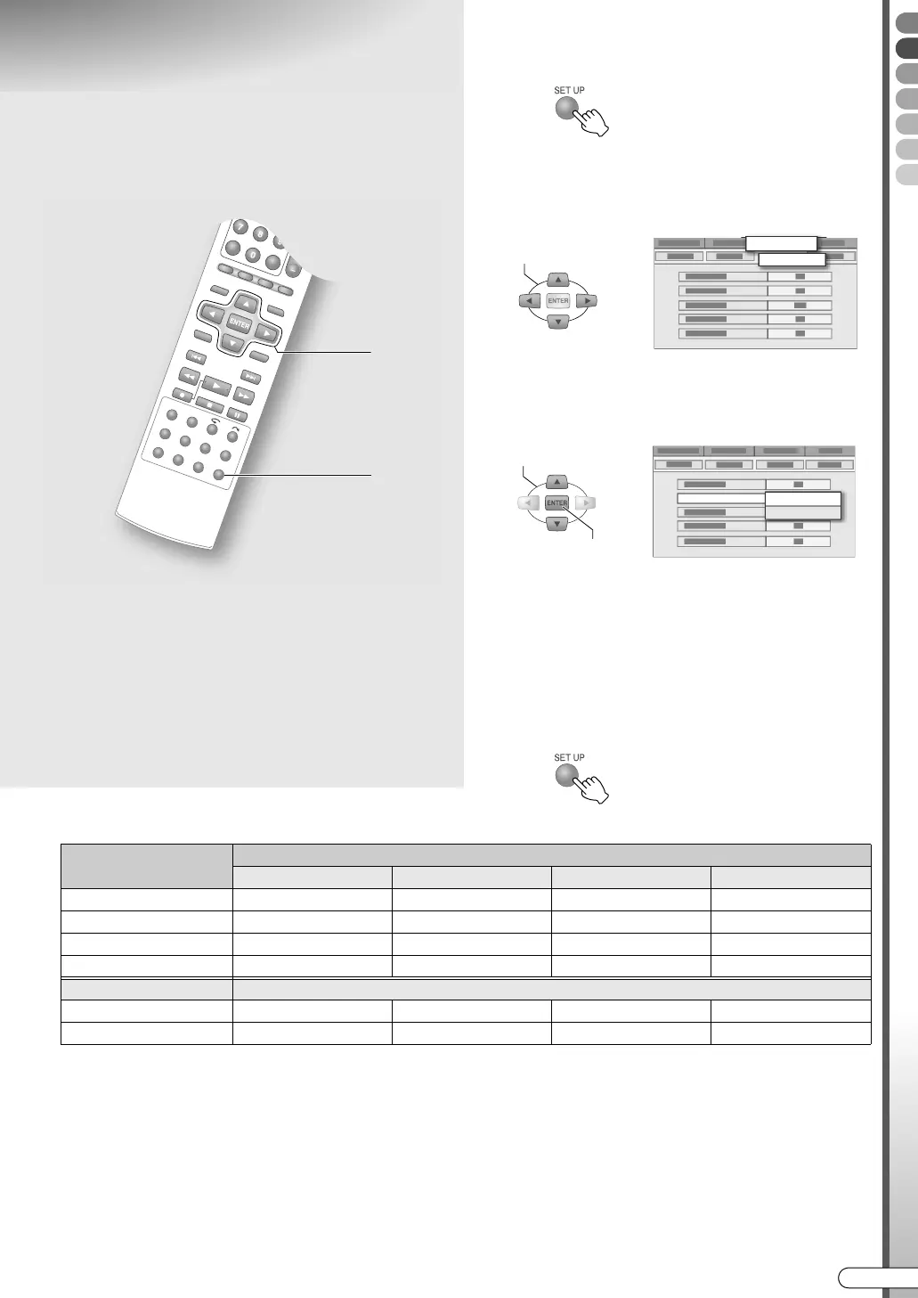
A Access the setup menu.
B Select “FUNCTION SET UP”.
C Select “VIDEO IN/OUT”.
D Set the input/output terminal.
A Select and confirm on AF-1 INPUTB.
B Select and confirm on AL-1 OUTPUTB.
C Select and confirm on AL-1 INPUTB.
D Select and confirm on AL-2 SELECTB.
0 See the description below for the combinations
of settings.
E Exit setup.
Possible combinations
*1 Switching to RGB signals is automatic.
*2 Component videos will be output from the [COMPONENT] terminal. Be sure to set to ACOMPONENTB if viewing via component
video.
*3 With this setting, signals from the [L-2 IN/DECODER] terminal will be output to the [L-1 IN/OUT] terminal even if this unit is
turned off, except during EPG data downloading.
*4 This setting cannot be made if AL-2 SELECTB is set to ASAT VIDEO/RGBB or ADECODERB.
9 The SCART connector supports the
connection of composite video signals.
Settings must correspond with the type of
video signal to use and the device to
connect.
........................................................
IMPORTANT:
0 For normal use, you can leave the default settings as
they are.
0 See the following page regarding each setting. Setup
Menu AF-1 INPUTB, AL-1 OUTPUTB, AL-1 INPUTB,
AL-2 SELECTB [ P114] h - k
0 During progressive scan, viewing is not possible as
the images are distorted.
A, E
B - D
SELECT
FUNCTION SET UP
VIDEO IN/OUT
SELECT
CONFIRM
F-1 INPUT
VIDEO
S-VIDEO
L-2 SELECT (*1)
L-1 OUTPUT
SCART VIDEO SCART S-VIDEO SCART RGB COMPONENT (*2)
VIDEO/RGB 3 3 3 3
S-VIDEO/RGB 3 3 3 3
SAT VIDEO/RGB 3 3 3 (*3)
DECODER 3 3 (*3)
L-1 INPUT
VIDEO 3 3 3 3
S-VIDEO 3 (*4) 3 (*4)
DR-MX10SE.book Page 29 Wednesday, December 14, 2005 3:37 PM

 Loading...