KaControl for Venkon
ASSEMBLY AND INSTALLATION INSTRUCTIONS
1.48
Venkon
21
6. Cabling
6.1 General Information
• All low voltage cables should be laid along the shortest route.
• Ensure that low voltage and high voltage cables are separated
using metal planking on cable trays.
• Only shielded cables should be used as low voltage and bus
cables.
• Lay all BUS cables in a linear pattern. Star-shaped wiring is not
permitted (Figure on left).
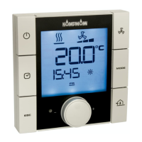
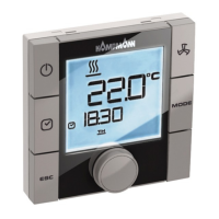
• The KaController is connected via a bus connection to the
respective Venkon and must be connected to the Venkon's PCB.
All BUS cables are shielded, paired cables, for instance CAT5
(AWG23), however must be at least of the same value.
When laying bus cables, avoid the formation star points, for
instance in the junction box. Instead loop the cables through
the units (Venkons).
Incorrect:
Star-shaped cabling of bus cables
Correct:
Line-shaped cabling of bus cables
 Loading...