TECHNICAL DESCRIPTION ULTRAFLOW
®
54 and 34
5512-385 GB/02.2014/Rev. H1
21
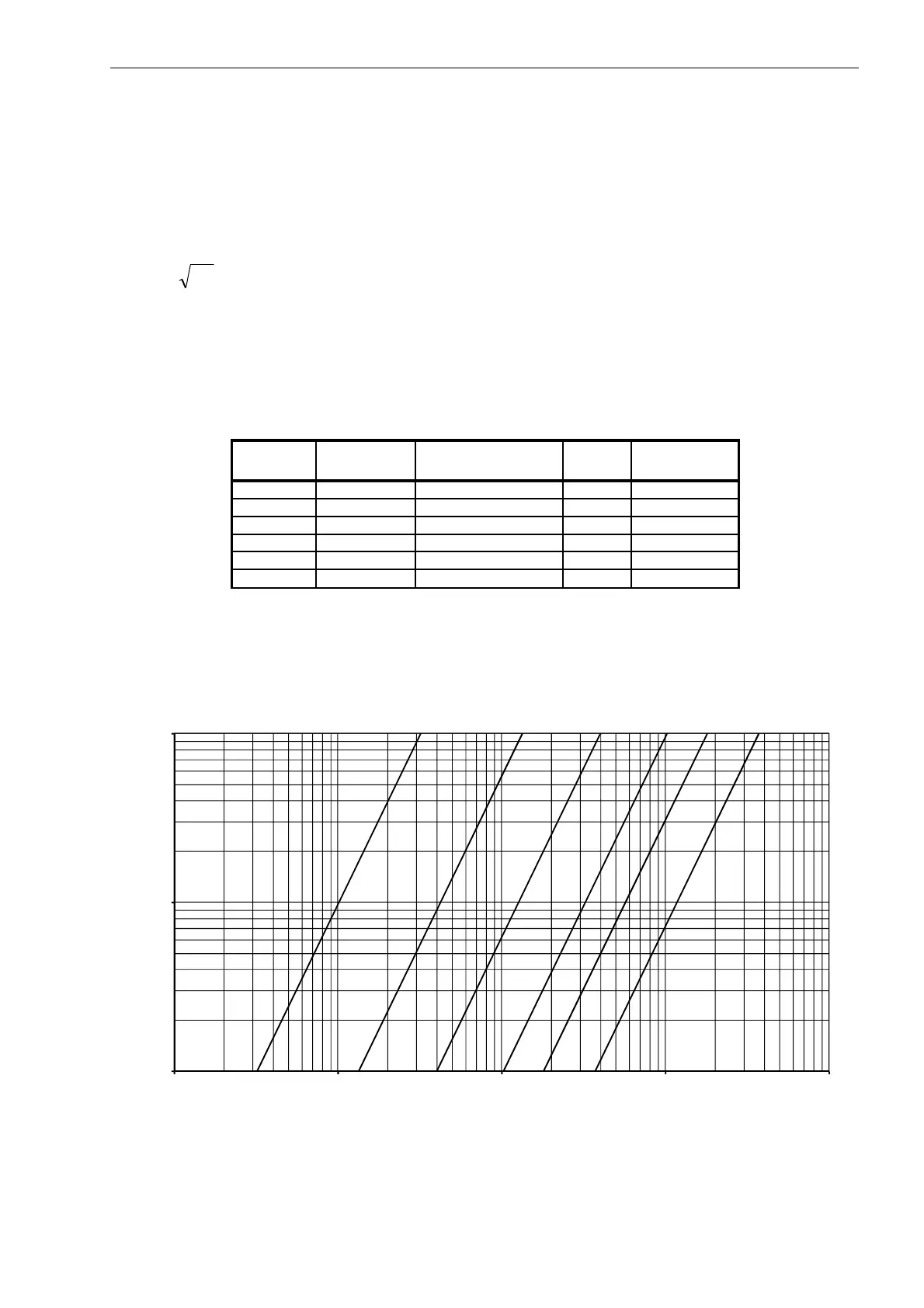
6 Pressure loss
The pressure loss in a flow sensor is stated as the maximum pressure loss at q
p
. According to EN 1434 the
maximum pressure loss must not exceed 0.25 bar, unless the energy meter includes a flow controller or functions
as pressure reducing equipment.
The pressure loss in a sensor increases with the square of the flow and can be stated as:
pkvQ ∆×=
where:
Q =volume flow rate [m³/h]
kv=volume flow rate at 1 bar pressure loss
∆p=pressure loss [bar]
q
Nom. diameter Q@0.25 bar
[m³/h] [mm] [m³/h]
A 0.6 & 1.5 DN15 & DN20 3.2 1.6
B 2.5 & 3.5 & 6 DN20, DN25 & DN32 13.4 6.7
C 10 & 15 DN40 & DN50 40 20
D 25 DN65 102 51
E 40 DN80 179 90
Graph kv
Table 15. Pressure loss table.
Diagram 1. Pressure loss chart for ULTRAFLOW
®
54 and 34.
0,01
0,1
1
0,1 1 10 100 1000
∆p [bar]
Flow [m³/h]
∆p ULTRAFLOW
®
54 and 34
A B C D E F

 Loading...


