TECHNICAL DESCRIPTION ULTRAFLOW
®
54 and 34
5512-385 GB/02.2014/Rev. H1
24
7.2 Straight inlet
ULTRAFLOW
®
54 requires neither straight inlet nor straight outlet to meet the Measuring Instruments Directive
(MID) 2004/22/ EC, OIML R75:2002 and EN 1434:2007. A straight inlet section will only be necessary in case of
heavy flow disturbances before the meter. We recommend following the guidelines of CEN CR 13582.
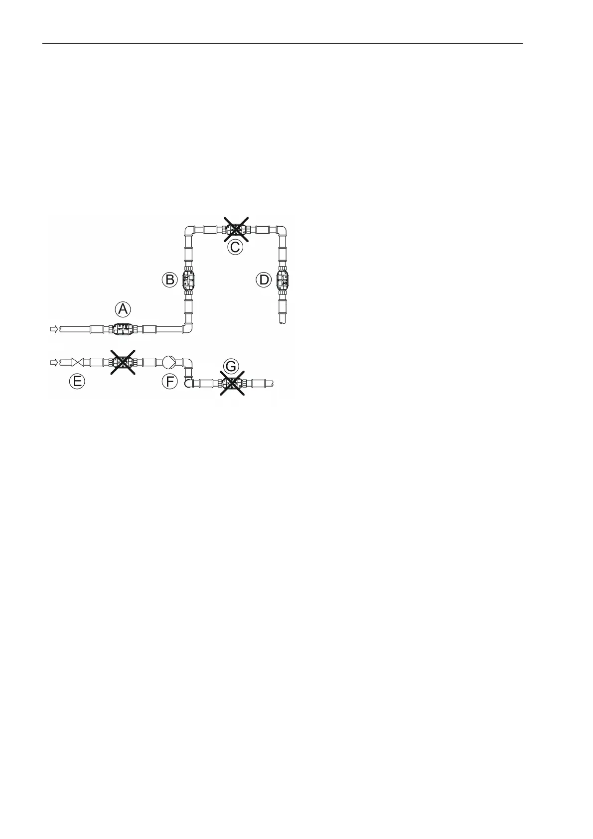
Optimal position can be obtained if you take the below-mentioned installation methods into consideration:
Figure 11
For general information concerning installation see CEN report DS/CEN/CR 13582, Heat meter Installation.
Instructions in selection, installation and use of heat meters.
7.3 Operating pressure
In order to prevent cavitation the back pressure at ULTRAFLOW
®
must be min. 1.5 bar at q
p
and min. 2.5 bar at q
s
.
This applies to temperatures up to approx. 80 °C. ULTRAFLOW
®
must not be exposed to pressure lower than the
ambient pressure (vacuum). For further information on operating pressure, see paragraph 8.7 Guidelines for
dimensioning ULTRAFLOW
®
.
A Recommended flow sensor position
B Recommended flow sensor position
C Unacceptable position due to risk of air
build-up
D Acceptable in closed systems.
Unacceptable position in open systems
due to risk of air build-up.
E A flow sensor should not be placed
immediately after a valve, except from
closing valves (ball valve type), which
must be completely open when not used
for closing
F A flow sensor should not be placed at the
inlet side of a pump
G A flow sensor should not be placed after a
double bend in two planes

 Loading...


