TECHNICAL DESCRIPTION ULTRAFLOW
®
54 and 34
5512-385 GB/02.2014/Rev. H1
45
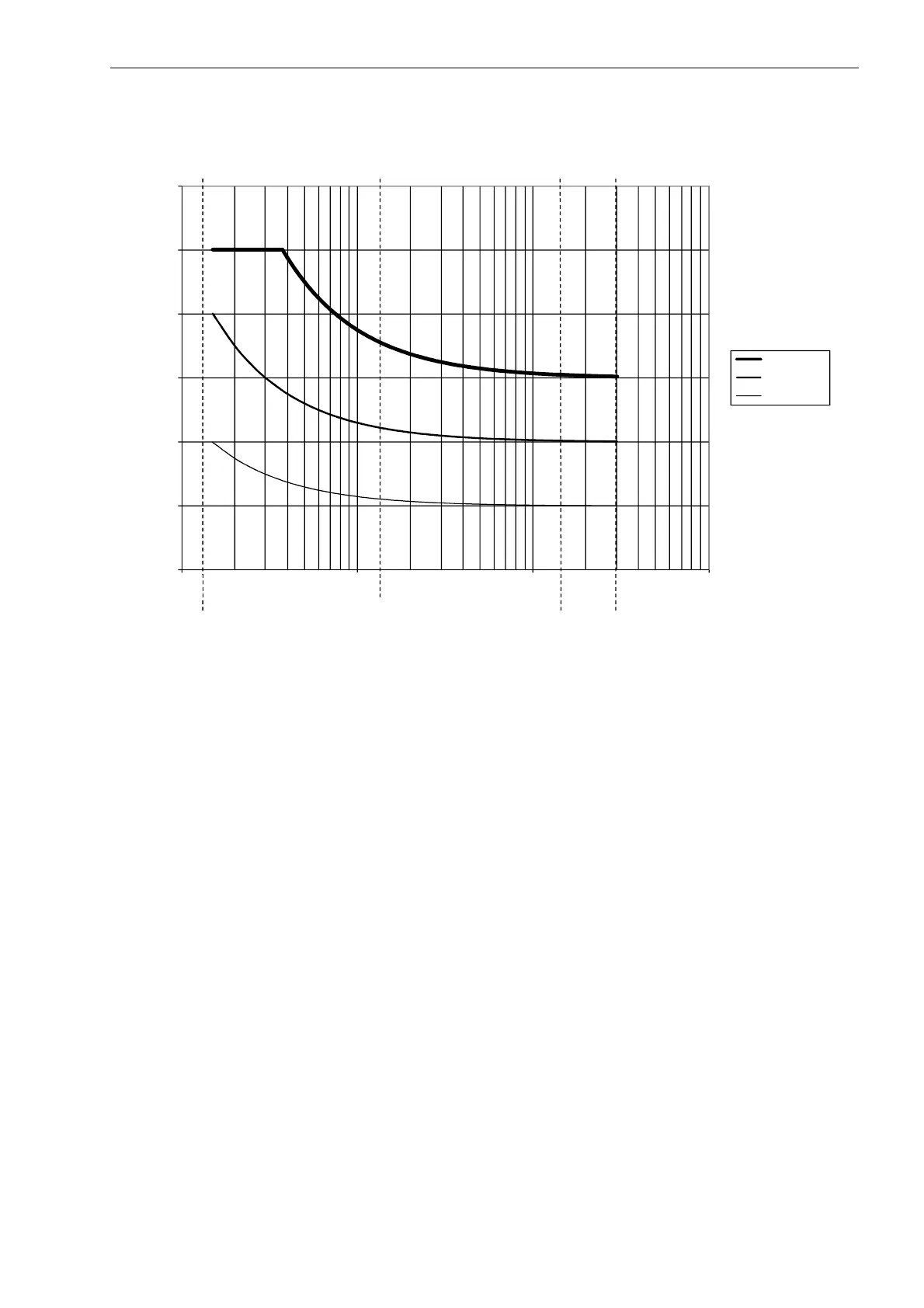
Diagram 14. Flow sensor tolerances q
i
:q
p
1:100 for q
p
1.5 m³/h.
8.12 Power consumption
The current consumption of ULTRAFLOW
®
is as follows:
Max. average 50 µA
Max. current 7 mA (max. 40 ms)
8.13 Interface connector/serial data
ULTRAFLOW
®
54 and 34 is fitted with a four-pole connector under the cover. Thus, it is not possible to access this
connector without breaking the seal. On delivery, the cover will be sealed with a factory seal and in connection
with verified sensors it will be a laboratory seal (legal seal).
The connector is used for:
• Programming sensor, including adjusting the flow curves by means of METERTOOL
• Setting the sensor to test mode
• Reading accumulated water quantity in connection with calibration
• External control of start/stop in connection with calibration
The interface connector is constructed as shown in Figure 30.
0
1
2
3
4
5
6
0,01 0,1 1 10
Tolerances [%]
Flow [m³/h]
Flow sensor tolerances qi:qp 1:100 (qp 1.5 m³/h)
EN1434 cl.3
qsqp0,1x qp
qi
0.01
0.1
0.1 x qp

 Loading...


