TECHNICAL DESCRIPTION ULTRAFLOW
®
54 and 34
5512-385 GB/02.2014/Rev. H1
26
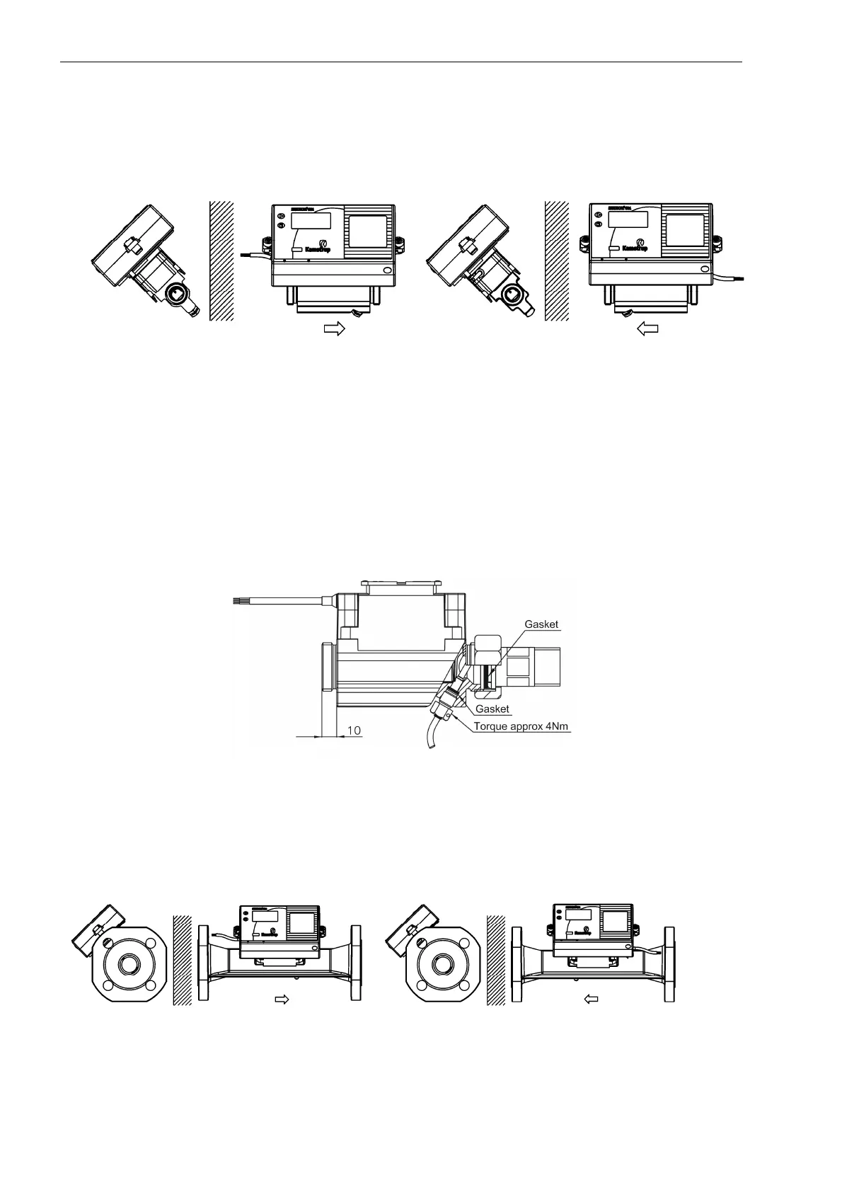
7.5 Installation examples
Figure 14. Threaded meter with MULTICAL
®
mounted on ULTRAFLOW
®
.
Glands and short direct sensor fitted into ULTRAFLOW
®
(only G¾B (R½) and G1B (R¾)).
The short direct sensor from Kamstrup can only be mounted in PN16 installations. The blind plug mounted in the
ULTRAFLOW
®
flow part can be used in connection with both PN16 and PN25.
The flow sensor can be used in both PN16 and PN25 installations and can be supplied marked either PN16 or
PN25 as desired.
Supplied glands, if any, can only be used for PN16. For PN25 installations shall be used suitable PN25 glands.
In connection with G¾Bx110 mm and G1Bx110 mm, it must be checked that 10 mm thread run-out is sufficient.
See Figure 15 below.
Figure 15. ULTRAFLOW
®
with gland and short direct sensor.
Figure 16. Flange meter with MULTICAL
®
mounted on ULTRAFLOW
®
.

 Loading...


