TECHNICAL DESCRIPTION ULTRAFLOW
®
54 and 34
5512-385 GB/02.2014/Rev. H1
43
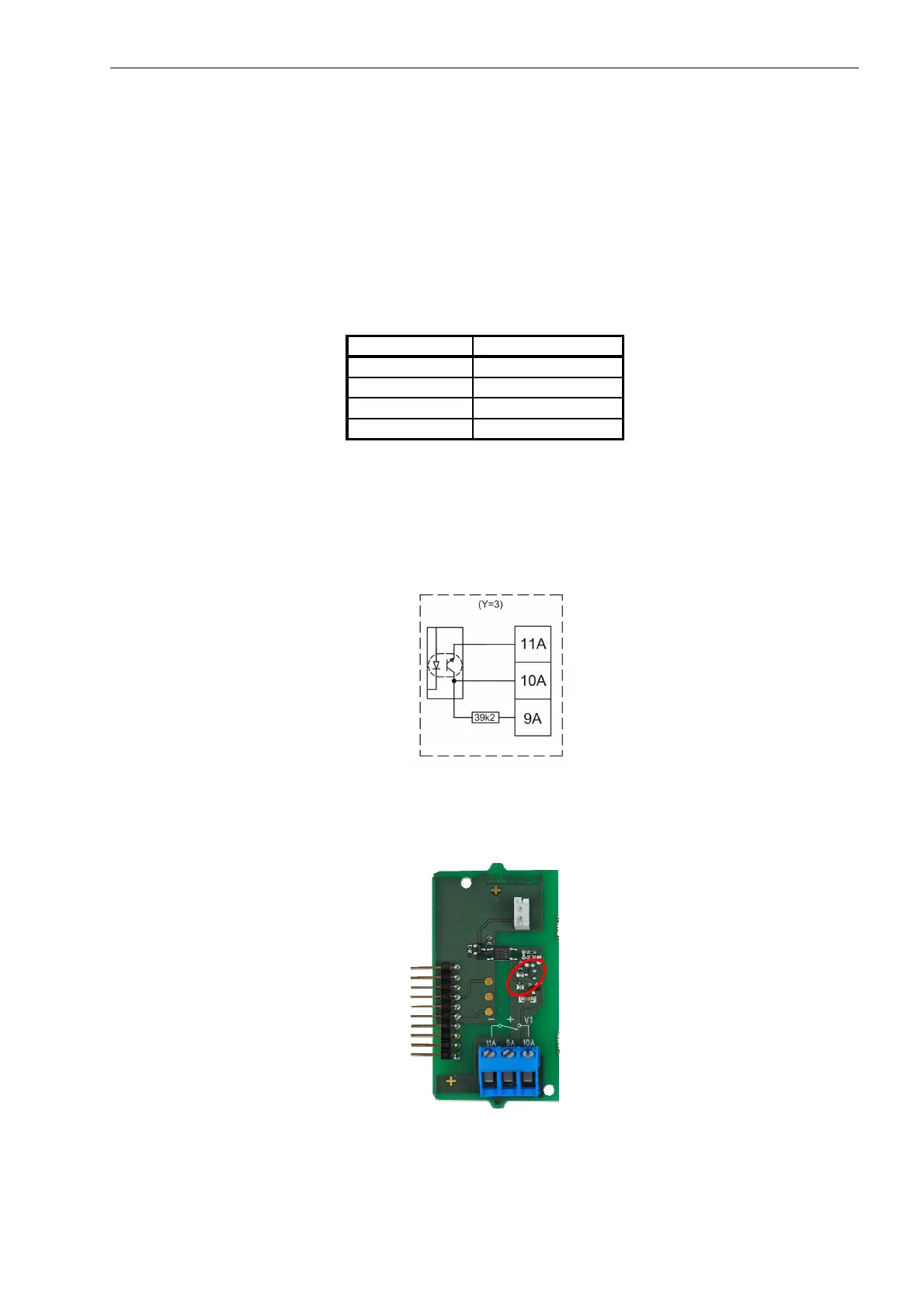
8.9.2 Galvanically separated output module (Y=3)
Pulse Transmitter/Pulse Divider is powered by the built-in supply module (Z=2, 7 or 8).
Cable length to Pulse Transmitter/Pulse Divider depends on calculator.
To calculator:
Type: Open collector.
Connection: Can be connected as three-wire via the built-in 39.2 kΩpull-up.
Module Y=3 OC and OD
Max input voltage 6 V
Max input current 0,1 mA
ON condition U ≤ 0,3 V @ 0,1 mA
OFF condition R ≥ 6 MΩ
Table 22
Concerning meter factor and pulse duration, see paragraph 4.6 Pulse Divider configuration CCC-DD-E-MMM.
Diagram 13. Block diagram for galvanically separated output module (Y=3).
Figure 29. Galvanically separated output module (Y=3). Note the omitted components
in the encircled area compared to output module (Y=2).

 Loading...


