TECHNICAL DESCRIPTION ULTRAFLOW
®
54 and 34
5512-385 GB/02.2014/Rev. H1
54
9.10 PULSE TESTER
During a calibration process it is often practical to use PULSE TESTER type 66-99-279 with the following functions:
Galvanically separated pulse outputs
Integral supply for ULTRAFLOW
LCD-display with counter
Externally controlled ”Hold” function
Can be fitted directly in a MULTICAL
base unit
9.10.1 Technical data for PULSE TESTER
Pulse inputs (M1/M2)
Counter inputs Max. frequency: 128 Hz
Active signal Amplitude: 2.5 - 5 Vpp
Pulse duration > 1 ms
Passive signal Internal pull-up 680 kΩ
Internal supply 3.65 V lithium battery
Note: There are one or two pulse inputs/outputs depending on the choice of base unit
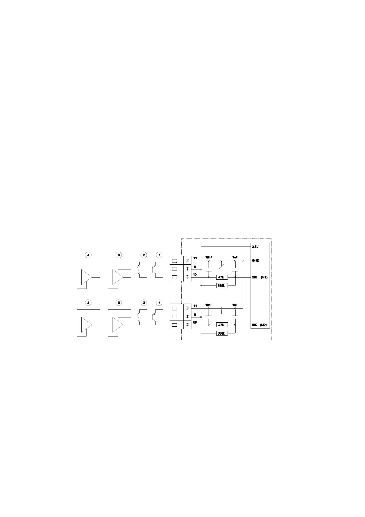
Figure 36
1 Flow sensor with transistor output
The transmitter is normally an optocoupler with FET or transistor output to be connected to terminals 10
and 11 for water meter M1 or terminals 69 and 11 for water meter M2.
The leak current of the transistor must not exceed 1 µA in off-state, and U
CE
in on-state must not exceed 0.5
VDC.
2 Flow sensor with relay or reed-switch output
The transmitter is a reed-switch, which is normally mounted on vane wheel and Woltmann meters, or the
relay output from e.g. MID-meters. This type of transmitter should not be used as the quick pulse input may
cause bounce problems.

 Loading...


