TECHNICAL DESCRIPTION ULTRAFLOW
®
54 and 34
5512-385 GB/02.2014/Rev. H1
55
3 Flow sensor with active pulse output, powered by the PULSE TESTER
This connection is used together with either Kamstrup’s ULTRAFLOW
or Kamstrup’s electronic pick-up for
vane wheel meters.
Connection (M1) 9: Red (9A) 10: Yellow (10A) 11: Blue (11A)
Connection (M2) 9: Red (9A) 69: Yellow (10A) 11: Blue (11A)
Table 28
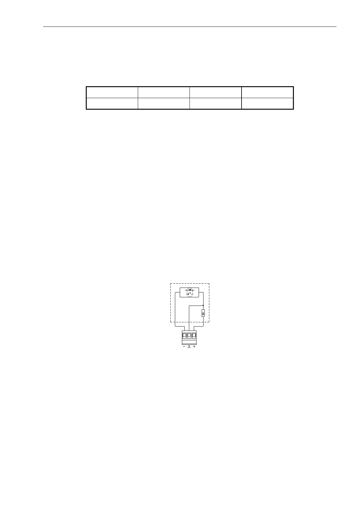
4 Flow sensor with active output and integral supply
Flow sensors with active signal output must be connected as shown in Figure 37. The signal level must be
between 3.5 and 5 V. Higher signal levels can be connected via a passive voltage divider, e.g. of 47 kΩ/10
kΩ at a signal level of 24 V.
Pulse outputs (M1/M2)
Two-wire connection:
Voltage < 24 V
Load > 1.5 kΩ
Three-wire connection
Voltage 5...30 V
Load > 5 kΩ
Figure 37
The outputs are galvanically separated and protected against overvoltage and reversed polarity.
Max. counter capacity before overflow is 9,999,999 counts.

 Loading...


