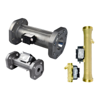
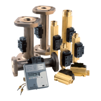
TECHNICAL DESCRIPTION ULTRAFLOW
®
54 and 34
5512-385 GB/02.2014/Rev. H1
8
2.3 Flow data
Nom. flow q
p
Nom. diameter
Meter factor
1)
Dynamic range
Flow@125 Hz
2)
∆
∆∆
∆
p@q
p
Min. cutoff
[m³/h] [mm] [imp/l]
q
i
:q
p
q
s
:q
p
[m³/h] [bar] [l/h]
0.6 DN15 & DN20 300 1:100 2:1 1.5 0.04 2
1.5 DN15 & DN20 100 1:100 2:1 4.5 0.22 3
2.5 DN20 60 1:100 2:1 7.5 0.03 5
3.5 DN25 50 1:100 2:1 9 0.07 7
6 DN25 & DN32 25 1:100 2:1 18 0.2 12
10 DN40 15 1:100 2:1 30 0.06 20
15 DN50 10 1:100 2:1 45 0.14 30
25 DN65 6 1:100 2:1 75 0.06 50
40 DN80 5 1:100 2:1 90 0.05 80
60 DN100 2.5 1:100 2:1 180 0.03 120
1)
The meter factor appears from the meter´s type label.
2)
Saturation flow (125 Hz. Max. pulse frequency 128 Hz is maintained at higher flow).
Table 1. Flow data.
2.4 Materials
Wetted parts
ULTRAFLOW
®
, q
p
0.6 and 1.5 m³/h
Housing, gland DZR brass (Dezincification resistant brass)
Housing, flange Stainless steel, W.no. 1.4308
Transducer Stainless steel, W.no. 1.4401
Gaskets EPDM
Reflectors Thermoplastic, PES 30 % GF and stainless steel, W.no. 1.4301
Measuring tube Thermoplastic, PES 30 % GF
ULTRAFLOW
®
, q
p
2.5 to 100 m³/h
Housing, gland DZR brass (Dezincification resistant brass)
Housing, flange Red brass, RG5 or stainless steel, W.no. 1.4308 (see par. 4 Ordering details)
Transducer Stainless steel, W.no. 1.4401
Gaskets EPDM
Reflectors Stainless steel, W.no. 1.4301
Measuring tube Thermoplastic, PES 30 % GF
Electronics housing, ULTRAFLOW
®
Base Thermoplastic, PBT 30 % GF
Cover Thermoplastic, PC 20 % GF
Housing, Pulse Transmitter/Pulse Divider
Base, cover Thermoplastic, PC 10 % GF
Signal cable
Silicone cable (3x0.5 mm
2
)
Mains supply cable 24/230 VAC (optional for mains supplied Pulse Transmitter/Pulse DIvider)
Cable with PVC-mantle (2x0.75 mm²)
 Loading...
