87
Appendix
Assembly Instructions
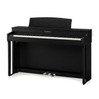
1. Attaching B and C to E
① Unfasten the pedal cable attached to E (one location only)
and extend the cable.
② Take the screws temporary mounted in E and set each one to
the metal groove of B and C, respectively.
③ Make sure that B and C are pressed against E without a gap.
Then, fasten the temporary mounting screws.
④ Insert the four silver tapping screws into the rest of the
holes. Tighten the screws to secure the panels in place.
B
E
③
②
d
B B
B B
E E
E
E
B
C
E
③
①
④
Pedal cable
Gaps
Temporary mounting screw
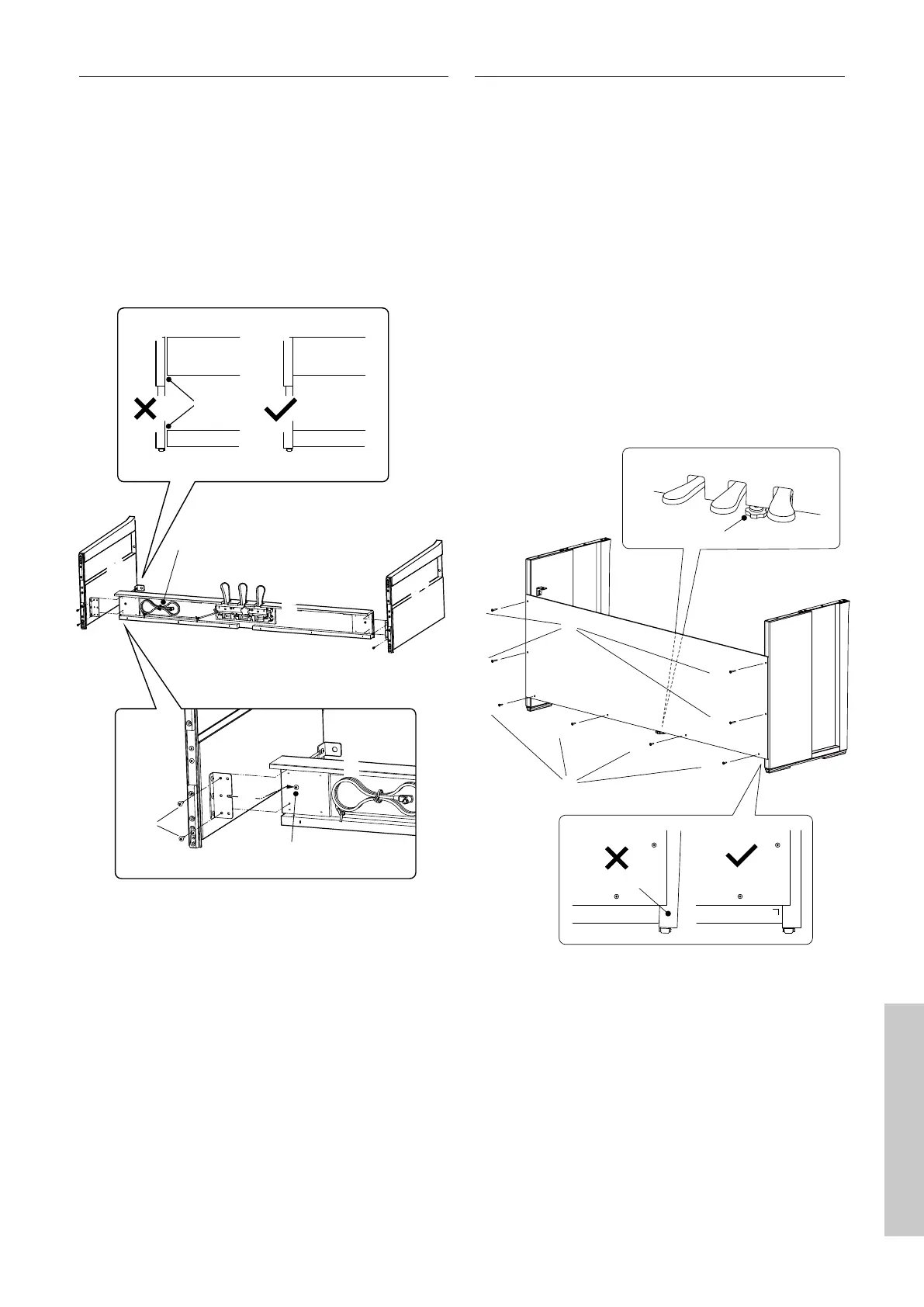
2. Attaching D
① Allow the E assembled with B and C to stand upright as
shown in the gure below.
Ensure that the adjustor is attached and the oor is
clear from parts or musical scores etc..
② Align the screw hole position of D to that of B and C. Use four
pieces of the long black tapping screws to set them in
place temporarily.
③ Align the screw hole position of D and E. Use four pieces of
the short black tapping screws to secure them in place.
④ Ensure that B and C are aligned with D without a gap, and
then fasten the temporarily mounted long black tapping
screws* to keep them in contact.
* For some of the body colours, silver screws are provid-
ed instead of black screws.
BB
CC
④
b
b
b
c
c
c
③
②
DD
c
Not aligned
Adjustor
①
 Loading...