148
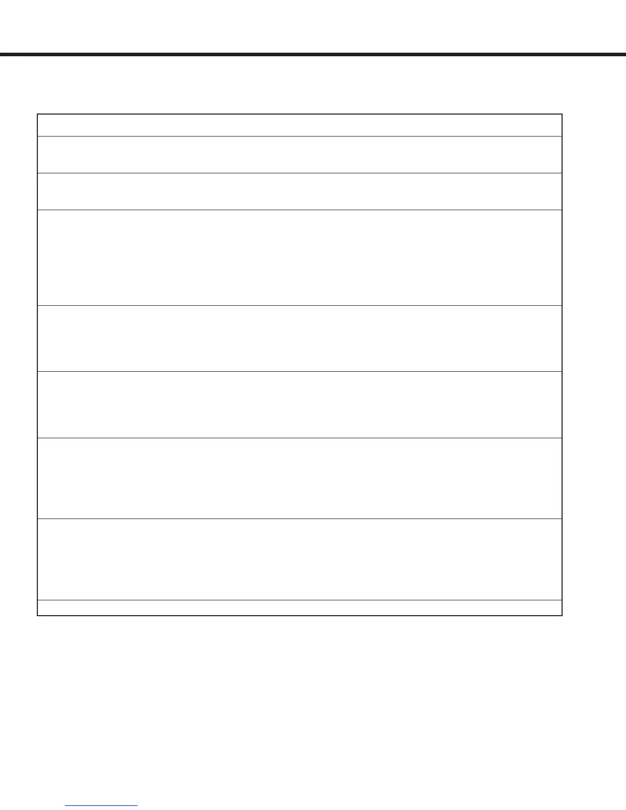
Designator Function
FLt Fault - indicates there is a drive fault. Output activates when there is a drive
fault, E.xxx
Rdy Ready - indicates the drive is ready for operation. Output activates when the
drive and ready for operation and there are no active faults E.xxx
dro Drive On - indicates the drive is on and in control of the motor. Output activates
after the following conditions are met: enable input active, direction input active,
motor phase current check passed, motor magnetizing current OK. The output
turns off when one of the following occurs: enable input is turned off, direction in-
put is turned off and timer LF.78 has expired, drive fault E.xx, current to the motor
is interrupted for any other reason.
ASd At Speed - indicates the actual speed is tracking the command speed. Output
is active as long as the actual speed matches the commanded speed. If during
operation the actual speed is greater than or less than the commanded value, the
output will turn off. See also parameters LF.57, LF.58, LF.59 for adjustment.
HSd High Speed Run - indicates when the actual motor speed is above twice the
value adjusted in LF. 41 (leveling speed). The output turns on when the actual
speed is greater than 2 x LF.41. When the actual speed drops below 1.5 times
LF.41 the output turns off. The speed is measured by the motor encoder.
brC Brake Control - for controlling the brake. Output activates after the following con-
ditions are met: enable input active, direction input active, motor phase current
check passed, motor magnetizing current OK. The output turns off when one of
the following occurs: enable input is turned off, direction input is turned off, drive
fault E.xx, current to the motor is interrupted for any other reason.
Mcc Main Contactor Control - for controlling the main motor contactor. Output acti-
vates after the following condition is met: enable input active. The output turns
off when one of the following occurs: enable input is turned off, drive fault E.xx.
Note: when using this input, it is necessary to qualify the direction signal(s)
through an auxiliary contact on the main contact for proper timing.
Switching conditions for the digital outputs. Only one condition can be assigned to each
output.
Input/Output Con guration

 Loading...


