33
10 11 17 18 19 20
GND
X2A
21 22 23
+
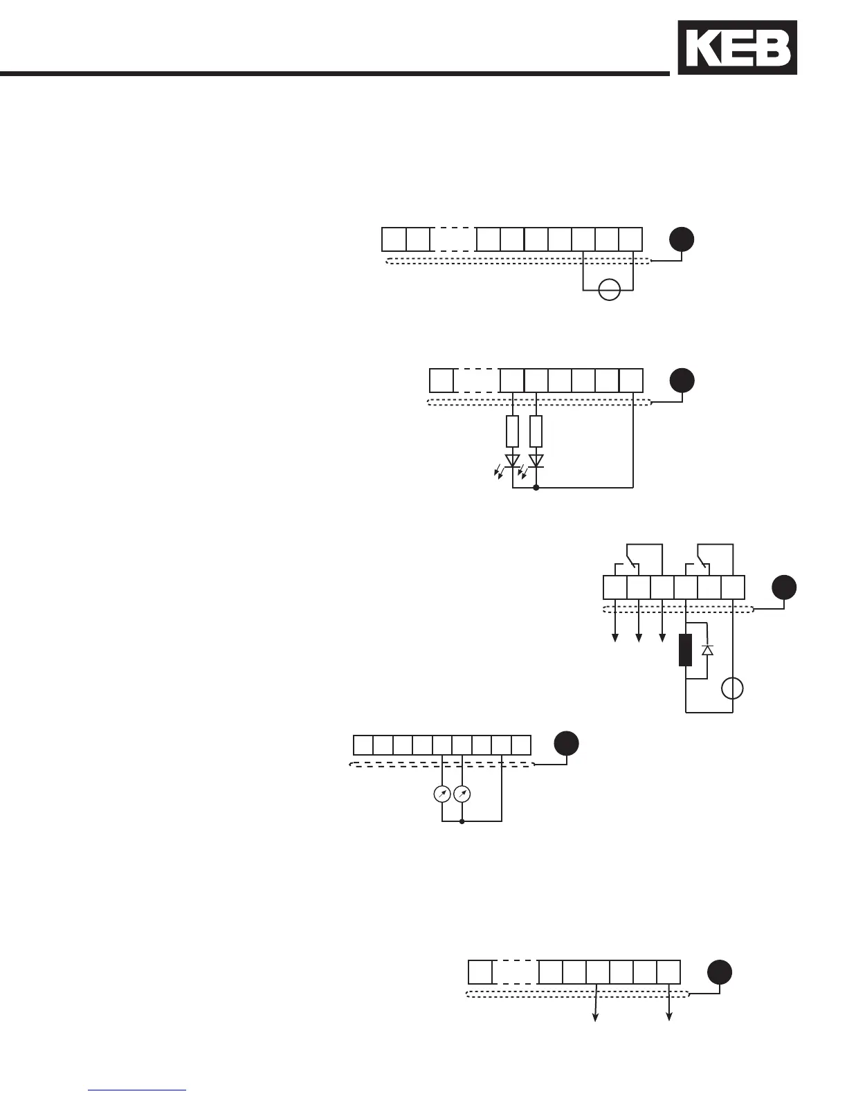
3.1.7 Relay Outputs
3.1.8 Analog Outputs
X2A
123456789
GND
0...±10 VDC
5 mA
3.1.6 Digital Outputs
10 18 19 20
GND
X2A
21 22 23
A total of max.
50 mA DC for
both outputs
3.1.9 Voltage Output
3.1.5 Voltage Input /
External Power Supply
The voltage output serves for triggering the digital inputs as well as for
suppling external control devices. Do not exceed the maximum output
current of 100 mA. This output is short circuit protected.
The supply to the control circuit through an external voltage source keeps
the control in operational condition even if the power stage is switched
off. To prevent unde ned conditions (false triggering), rst switch on the
power supply then the inverter.
20...30V ±0%, 1 A DC regulated
10 18 19 20
GND
X2A
21 22 23
+
-
0 V
comV
out = Approx. 24V / max.100 mA
24 25 26
GND
X2A
27 28 29
approx. 30 VDC / 1 A
+
-
In case of inductive loads on the
relay outputs, protective wiring must
be provided (e.g. RC or diode arc
suppression)!
Installation and Connection

 Loading...


