52
The Elevator drive uses a special operator which provides a user interface
and functionality speci c to elevator applications. The operator must be
plugged into the drive in order for the drive to function correctly.
Unplugging the operator while the drive is in operation will result
in immediate shutdown of the drive and will cause the ready relay
to drop and the fault output to activate. If it is necessary to remove
the operator, do so while the elevator is standing still!
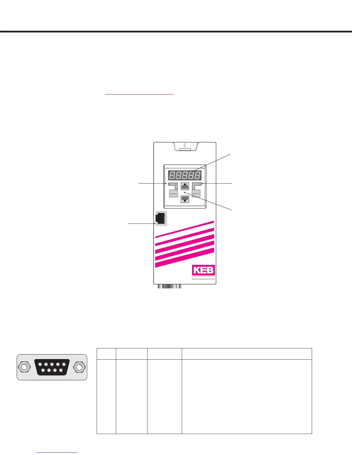
4. Operation of the unit
Double function keypad
Operating-Error display
Normal “LED on”
Error “LED blinks”
5-digit LED Display
4.1 Digital Operator
PIN RS485 Signal Meaning
1 – – reserved
2 – TxD Transmitter signal, RS232
3 – RxD Receiver signal, RS232
4 A’ RxD-A Receiver signal A, RS485
5 B’ RxD-B Receiver signal B, RS485
6 – VP Voltage supply-Plus +5V (I
max
= 10 mA)
7 C, C’ DGND Data reference potential
8 A TxD-A Transmitter signal A, RS485
9 B TxD-B Transmitter signal B, RS485
Interface control
Transmit “LED on”
Use only the operator interface X6C for the serial data transfer using
RS232, or 485. The direct connection from PC directly to the Elevator
Drive without operator or using the HSP5 diagnostic port is only possible
with a special cable. Incorrect cabling can lead to the destruction of the
PC-interface. Consult the factory for more information.
RS232, RS485
54321
9876
HSP5 diagnostic port
X6C
RS232, RS485
START
FUNC.
SPEED
ENTER
F/R
STOP
COMBIVERT
X6C X6D
X6B
Elevator Operator: Part No. 00.F5.060-2029

 Loading...


