34
3.2 Encoder
Connections
3.2.1 X3A RS422/TTL
Incremental Encoder
Input
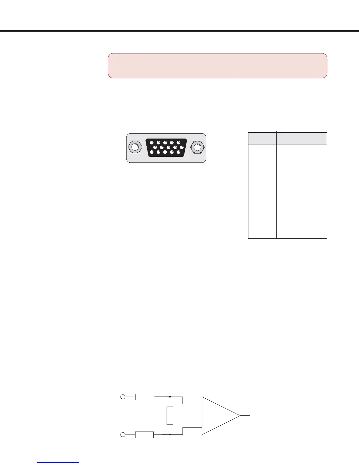
Connect the incremental encoder mounted on the motor to the 15-pin
Sub-D connector at X3A on the COMBIVERT F5M. This connection
provides speed feedback and is imperative to the proper operation of
the F5.
Input Wiring
A +
B +
A -
B -
approx.
120
5432 1
10 9 8 7 6
15 14 13 12 11
5.2 V x I
+5V
I
var
= 170 mA - –————
V
var
Pin No. Signal
3 A-
4 B-
8 A+
9 B+
11 V
var
24...30 V
12 +5.2 V
13 0V (com)
14 N-
15 N+
Shield Housing
ONLY when the inverter is switched off and the voltage
supply is disconnected may the feedback connectors
be removed or connected!
The internal voltage of "V
var
" 24...30 V
(1)
is an unregulated supply and will allow up
to 170 mA max. current draw, for X3A and
X3B total. If higher voltages / currents are
required, then an external power supply
must be provided.
The +5.2 V is a regulated voltage supply
generated from V
var
and will allow up to
500 mA max. current draw, for X3A and
X3B total. If additional current is required
from the +5.2 V output, the current from
V
var
decreases in accordance with following
formula:
The following speci cations apply to encoder interface X3A and X3B, channel
1 and 2 respectively:
• Max. operating frequency: 300 kHz.
• Internal terminating resistance: R
t
= 120
• RS422 or TTL level square wave
voltage level: 2...5 Vdc
approx.
34
Installation and Connection

 Loading...


