23
Technical Data
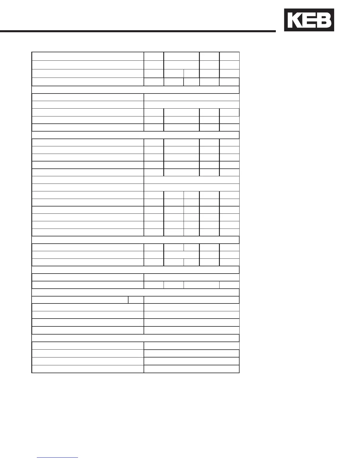
Inverter Size
16 17 18 19
Recommended Motor Power
[hp] 20 25 30 40
Housing size
GGHHH
Unit Hardware 2 2 2 2 2
Input Ratings
Supply voltage [V] 305...528 ±0 (480 V Nominal voltage
)
Supply voltage frequency [Hz] 50 / 60 +/- 2
Input phases 3
3
3
3
Rated input current [A] 35 44 52 57
Recommended wire gauge
1)
[awg] 8 6 6 4
Output Ratings
Rated output power [kVA] 23 29 35 42
Rated motor power [kW] 15 18.5 22 30
Rated output current [A] 27 34 40 52
Peak current (30 seconds)
2)
[A] 49.5 63 75 90
Over current fault (E.OC) trip level [A] 59.4 75.6 90 108
Output voltage [V] 3 x 0…Vsupply
Output frequency [Hz] Generally 0 to 599Hz (limited by carrier frequency)
Rated switching frequency
3)
[kHz] 8 4 8 8 8
Maximum switching frequency [kHz] 16 16 16 16 16
Power loss at rated operation
4)
[W] 310 360 470 610 540
Stall current at 4kHz [A] 33 42 42 60 60
Stall current at 8kHz [A] 21.5 21.5 42 50 54
Stall current at 16kHz [A] 9.5 - 25 30 36
Braking Circuit
Min. braking resistance [Ohm] 25 25 9 9 9
Typ. braking resistance [Ohm] 39 28 22 16
Max. braking current [A] 30 30 90 90 90
Installation Information
Max. shielded motor cable length
5)
[ft] 330
Tightening torque for power terminals [in lb] 11 11 35 35
Environmental
Max. heat sink temperature TOH [°C] 90°C / 194°F
Storage temperature [°C] -25...70 °C / -13…158°F
Operating temperature [°C] -10...45 °C / 14…113°F
Housing design / protection Chassis / IP20 / Pollution Degree 2
Relative humidity max. 95% without condensation
Approvals
Tested in accordance with… EN 61800-3 /UL508C
Standards for emitted interference EN 55011 Class B / EN 55022 Class A
Standards for noise immunity IEC 1000-4-2 / -3 / -4 / -5/ -6
Climatic category 3K3 in accordance with EN 50178
1) The wire gauge is based on the maximum fuse rating, copper wire with a 75°C insulation rating, THHW or equivalent. If circuit protection is selected
based on the actual input current, the wire size could be reduced.
2) This is the peak output current limited by hardware regulation. The software current control reserves 5% for closed loop regulation.
3) This is the maximum carrier frequency the power stage can support. The actual operating carrier frequency is adjusted and limited by the control
card.
4) This is the power dissipation at the rated carrier frequency, rated voltage and rated load. Operation at reduced carrier frequencies or reduced load
will decrease this value.
5) Max motor cable length when using shielded cable, KEB EMI lter, and the installation must conform to EN55011 / EN55022.

 Loading...


