28
T1
T2
T1
T2
PA
PB
++
PB
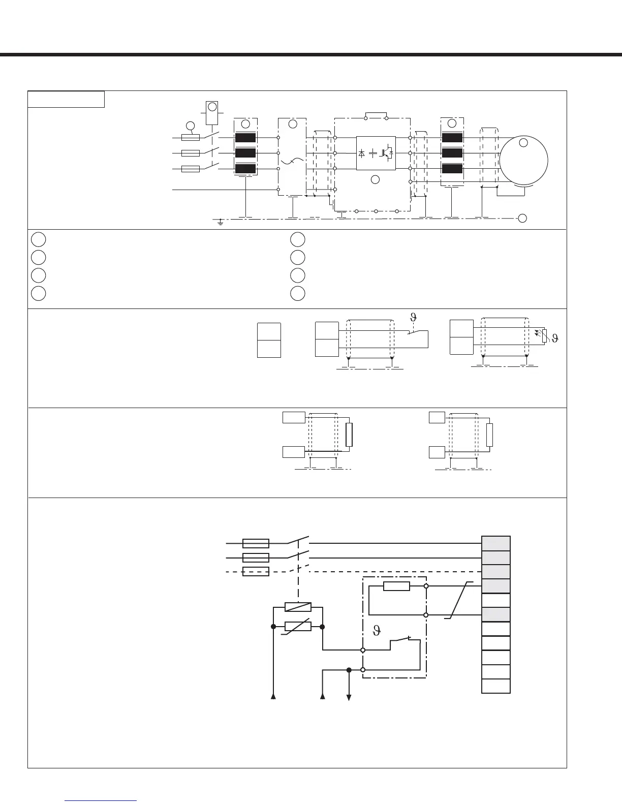
Connection of braking resistor
(Braking circuit installed as standard in
housing sizes E,G,H, R and U.)
External motor temperature sensor
(for all units)
Thermal switch
(NC-contact)
No jumper required, when
a sensor is not connected
Temperature sensor (PTC )
1650...4k tripping resistance
750...1650 reset resistance
use with wiring diagram 2
use with wiring diagram 1
Don't install sensor wires with control wires!
Must use double shield when running these
wires with motor wires!
It is necessary to activate this function via
software parameter! See US.33
Wiring diagram 3
L1
L2
L3
L1
L2
U
V
W
M
3
~
T1
T2
U
V
W
U1
V1
W1
L1
L2
L3
(+)PA
PB
+
3
2
4
1
5
7
8
6
-
L3
GND
GND
GND
GND
GND
Connection of the Power Circuit
U
V
W
PB
L3
N/L2
X1A
T1
T2
--
L1
++
PA
PB
OH1
OH2
U
= 90°C
Braking resistor
with line side over
temperature cutoff
This is the only way to turn
off voltage to the resistor in
the event of failure of the
internal braking transistor of
the inverter.
24VDC or 120VAC contactor control voltage
Note: a NC thermal switch not PTC device on the resistor is required.
1
Supply fuse
5
COMBIVERT F5
2
Disconnect switch or contactor
6
Motor choke or output fi lter
3
Line choke
7
Motor
4
Interference suppression fi lter
8
Sub panel in control cabinet

 Loading...


