39
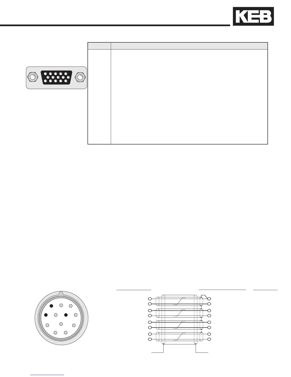
54321
10 9 8 7 6
15 14 13 12 11
Max. Load Capacity depending on Voltage Supply
Max. load capacity at +7.5 V:300 mA. The speci ed current is reduced by the load current taken
from the second encoder interface X3B interface (see section 3.2.6).
Pre-manufactured Hiperface cables offer the best solution against noise and disturbance while at
the same time saving installation time. The cables come in standard lengths of 5m,10m,15m,20m,
25m, and 30m.
Cable Part Number
00.S4.809-00xx xx = length in meters, 10 = 10 meters
Mating Connector
00.90.912-003U for encoder (solder type)
Running in Conduit
When this cable must be pulled through metallic conduit, it is necessary to over size the
conduit! Use of a 1 1/2 inch trade size conduit will allow the connectors to pass without removal of
the connectors. Cutting the cable, or removal of the connectors or their housings voids the warranty
and will result in problems with electrical noise after the fact.
Drive connection
X3A Female SUBD
15 HD
Circular connector on
HIPERFACE encoder.
1
2
3
4
5
6
7
8
9
12
10
11
4 REF_SIN red
9 SIN + blue
14 DATA - pink
15 DATA + gray
3 REF_COS yellow
8 COS + green
Shield wire tied to housing
Wire color
13 0V (com) white
10 +7.5V brown
Shield wire tied to housing
which is earth ground.
Encoder pin-out
X3A pin-out channel 1
REF_SIN 4
SIN + 8
DATA - 7
DATA + 6
REF_COS 5
COS + 9
GND 11
+7.5V 10
Note: Inner pair shields are tied to 0V (com),
pin 13, not earth ground!
HIPERFACE Cable
Pin No Signal Description
1 - -
2 - -
3 REF_COS signal input A- (difference signal to COS+)
4 REF_SIN signal input B- (difference signal to SIN+)
5 - -
6 - -
7 - -
8 COS+ signal input A (absolute track for counter and direction detection)
9 SIN+ signal input B (absolute track for counter and direction detection)
10 +7.5V Supply voltage for encoder
11 - -
12 - -
13 COM reference potential for supply voltage
14 -DATA Data channel RS485
15 +DATA Data channel RS485
Installation and Connection

 Loading...


