84
Digital speed setting uses preset digital values in the drive as
command speeds. The drive creates the driving pro le between
selected speeds.
Symbol: 1 = Input is active
0 = Input is not active
X = Setting has no effect or don’t care
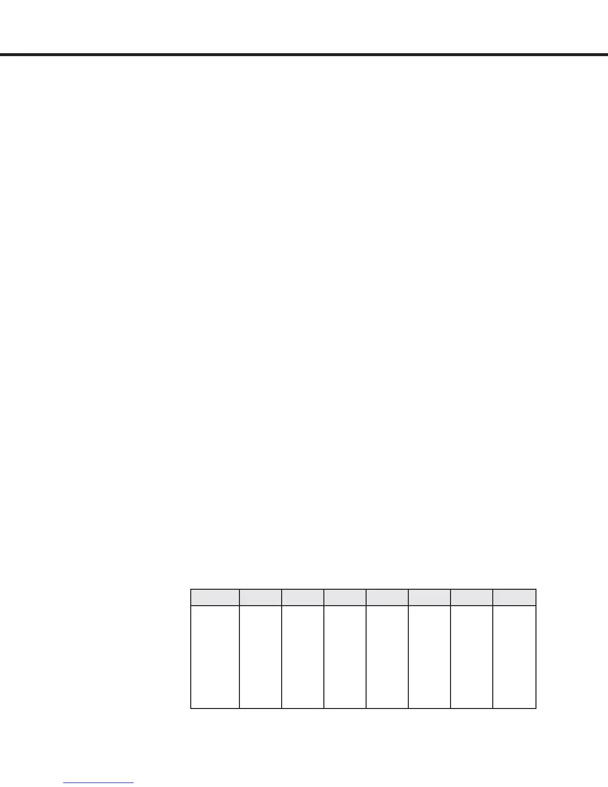
b) Input coded set speed selection LF.02 = d SPd
X2A.10 X2A.11 X2A.12 X2A.13
Speed =0 0 0 0 0
S
Leveling
1 0 x x
S
High Leveling
0 1 x x
S
Intermediate
1 1 x x
S
High
0 0 1 x
S
Inspection
0 0 0 1
A unipolar analog signal is connected to the terminals
X2A.1(+) and X2A.2 (-). Terminals X2A.3 and X2A.4 can be
used for pre-torque input. Additionally with this setting the
analog output (X2A.5) for motor speed becomes unipolar
as well.
0 ... 10V = 0 ... max. system speed (LF.20)
Terminals X2A.14 and X2A.15 are used to select direction
and activate the start and stop routine. The directions below
must be followed in the exact sequence they are listed:
Start: 1.) Enable on X2A.16=on
2.) “Direction” input terminal (X2A.14 = on
or X2A.15 = on)
3.) Drive commences current check and
magnetizes the motor when ready it will
activate the DRO output X2A.27...29.
4.) Give analog speed signal
Stop: 1.) Analog signal => 0V
2.) Terminal X2A.14 / X2A.15 = off
3.) Enable X2A.16=off after the sum of the
times adjusted in LF.78 and LF.79.
a) Analog set speed selection LF.02 = AbSPd
Parameter Description - Basic Set Up

 Loading...


